4507
Determination of the dielectric constant for RF passive shimming at 4T MRI
Mohan Lal Jayatilake1,2, Christopher T Sica2,3, Rommy Elyan2, Rang Pang1, Dhevin Karunanayaka2, Anupa Ekanayaka4, and Prasanna Karunanayaka2,5
1Department of Neurosurgery, Pennsylvania State University, Hershey, PA, United States, 2Center for Nuclear Magnetic Resonance Research, Pennsylvania State University, Hershey, PA, United States, 3Department of Engineering Science and Mechanics, Pennsylvania State University, University Park, State College, PA, United States, 4Grodno State Medical University, Grodno, Belarus, 5Department of Radiology, Pennsylvania State University, Hershey, PA, United States
1Department of Neurosurgery, Pennsylvania State University, Hershey, PA, United States, 2Center for Nuclear Magnetic Resonance Research, Pennsylvania State University, Hershey, PA, United States, 3Department of Engineering Science and Mechanics, Pennsylvania State University, University Park, State College, PA, United States, 4Grodno State Medical University, Grodno, Belarus, 5Department of Radiology, Pennsylvania State University, Hershey, PA, United States
Synopsis
Optimal image quality for Magnetic Resonance Imaging (MRI) at high fields requires a homogeneous RF (B1) field; however, the dielectric properties of the human brain results in B1 field inhomogeneities, and signal loss at the periphery of the head. Selecting the appropriate permittivity and quantity of material for the shim is essential. Here, we introduce a theoretical framework for determining the requisite dielectric constant of the passive shim material directly.
INTRODUCTION
Optimal image quality for MRI at high-fields requires a homogeneous B1 field; however, the dielectric properties of the human brain result in B1 field inhomogeneity and signal loss at the periphery of the head. These results from constructive and destructive RF interactions (i.e.,complex wave behavior) which become worse with increasing magnetic field strengths. The placement of a shim object, with a high-dielectric constant adjacent to the body, has been proposed as a method for reducing B1 inhomogeneity by altering wave propagation within the volume of interest1,2. Selecting the appropriate permittivity and quantity of shim material is essential3. Previous work has determined the dielectric properties of the shim empirically3,4. In this work, we introduce a theoretical framework for computing the dielectric constant of the passive shim materials by increasing the axial or minimizing the radial propagation constants.THEORY AND METHODS
The head is assumed as a cylindrical-shaped object; the axes of the head, coil, and shield have concentric radii of r1=20, r2=28, and r3=34(cm) respectively (Fig.1). The subscripted numbers 1,2, and 3 represent the regions of the brain, brain-to–coil, and coil-to-shield. The permittivity and conductivity of the brain are εb, and σ, respectively. Both brain-to-coil and coil-to-shield regions have the permittivity of air (ε0). It is assumed that the electromagnetic field propagates in the z-direction. At r=r1, r2, and r3, the propagating RF fields satisfy different boundary conditions. After applying the boundary conditions, a relationship between amplitude coefficients in different regions of the general wave solution can be determined. Based on the amplitude coefficients’ correlation, the characteristic equation can be determined. The following is the simplified version of characteristic equation4.$$$r1^2kz^2kρ^2(k^2−k0^2)(r2^2−r1^2)α + kρ^2kρ0^2(2k^2kρ0^2(r2^2−r1^2)+kρ^2kρ0^2(r2^2+r1^2))(r1^2kz^2kρ^2α'−kρ0^2α)=0$$$[1]
k and k0 are the propagation constants in the brain and air; kz and kρ are axial and radial propagation constants that characterize the RF field amplitude distribution within the brain. α and α’ are defined below.
$$$α=-2(r1^2+πr2)/π^2r1r3^3kρ0$$$[2];
$$$α'=-2(r1+πkρ0r3^2)/π^2r1r2r3^2kρ0$$$[3]
kρ and kρ0 depend on the dielectric properties within the brain and brain-to-coil region.
$$$kρ^2=k^2-kz^2$$$[4];
$$$kρ0^2=k0^2-kz^2$$$[5]
The brain-to-coil space is filled with air, which is why kz is relatively small while kρ is relatively large at higher frequencies. This causes to experience small wavelength and large amplitude variations of the B1 magnetic field. The large variation in RF field amplitude results in B1 field inhomogeneity within the brain. RF field homogeneity can be improved by either minimizing kρ, which is impractical due to the unchanging dielectric and conductive properties in the brain, or by increasing kz. Loading, with the high dielectric material into the brain-to-coil region, significantly influences the propagation characteristics of the head coil, as demonstrated by the changes in kz. The characteristic equation allows one to determine the requisite effective dielectric constant (ε) for the loading substance, which is essential for enhancing RF field homogeneity. A healthy subject was recruited and consented to participate in this study, and a bag containing a suspension of 22.5% v/v Calcium titanate (CaTiO3) in de-ionized water (to attain the effective dielectric constant of 92–94 of the suspension) was placed on the left side of the head. A 3D gradient-echo pulse sequence was used to obtain maps of the brain. Acquisition parameters: TE=5.25 and 7ms, TR=16ms, 10° flip, 256x256x256mm FOV, 128x64x64 matrix) on a 4T Varian INOVA whole-body MRI
RESULTS
The Eq.[1] can be modified as a function of kz and kρ using Eqs.[2],[3],[4] and [5]. An expression for the kz can be derived as a function of the kρ following factorization of the modified characteristic equation. Based on the correlation between kρ and kz (Fig.2A), the minimum kρ of 0.34cm-1 is obtained at the maximum kz of 1.82cm-1at 4T. Additionally, at the first maximum of kz, the radial wavelength (λρ=2π/kρ) is about 18.5cm which is comparable to the size of the brain. Furthermore, Eq.[1] can also be expressed as a function of kz and effective ε in the body-to-coil region, which is defined as g(kz,ε). According to Fig.2B, the range of magnitude of effective ε constant is between 92-94 corresponding to a kz of 1.82cm-1 when the g(kz,ε) reaches zero. Fig.3 shows the simulated RF field map after filling the body-to-coil region with (A) air, (B) an arbitrary chosen dielectric material (ε=48), and (C) a dielectric material (ε=94), which is obtained based on Eq.[1]. The field map is normalized to the field amplitude at the center of the FOV with the assumption that the entire brain has a uniform dielectric constant of εb=58. The results clearly show that the ripples of the RF field distribution within the brain were significantly reduced as the ε within the body-to-coil region increased. Fig.4 illustrates the enhancement of signal intensity with the introduction of the suspension placed on the left side of the subject.DISCUSSION AND CONCLUSION
The measured results (Fig.4), indicate that this method provides an effective approach towards improving RF field homogeneity within the brain. With the introduction of high dielectric material, the kz can be changed. This allows one to change the kρ appropriately. The accurate estimation of effective ε diminishes RF field inhomogeneity across the brain. Incorrect estimation of the dielectric properties of the suspension may diminish signal intensity over the entire brain due to inhomogeneous B1 field.Acknowledgements
We thank the Center for NMR Research and Center for Aging and Neurodegenerative Diseases of Penn State University College of Medicine for all the staffs' kind help and suggestion. This research is supported by the National Institute on Aging grants (1R01AG070088-01A1 and1R21AG064486)References
[1] Haines et al., J Magn Reson Imaging 203;323-327 (2010). [2] Foo et al., Magn Reson Med 23:287– 301(1992). [3] Foo et al., Magn Reson Med 21:165–177(1991). [4] Yang et al.,J Magn Reson Imaging 24;197–202(2006). [5] Yang et al., J Magn Reson Imaging 47;982–989(2002).Figures
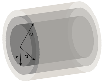
Figure 1 A
long cylindrical model used to determine requisite dielectric properties of the
passive shim material for B1 passive shimming within the
human brain.
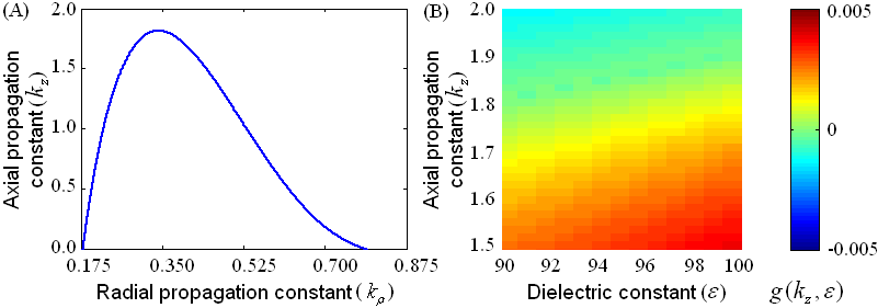
Figure 2 (A) Correlation of
axial vs. radial propagation constant. (B) Distribution of the modified
characteristic equation g(kz,ε) according to variations
of axial propagation and dielectric constants.
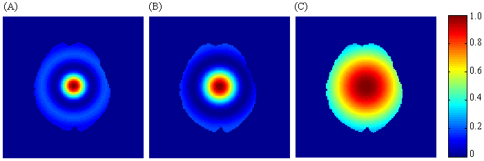
Figure 3 The RF field distributions for axial slices of
the subject’s brain.
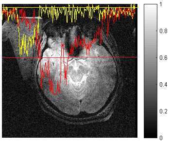
Figure 4 The
measured, normalized, signal intensity map comparison for the human brain for
baseline (yellow line from left to right) (a) and with a suspension of a dielectric
constant of 92-94 (red line from left to right) (b) at the axial view. The
suspension was placed on the left side of the subject’s head.
DOI: https://doi.org/10.58530/2022/4507