4505
Development of high impedance microstrip resonators for ultrahigh field MR imaging
Tianyu Gao1 and Xiaoliang Zhang2
1Biomedical engineering, University at buffalo, buffalo, NY, United States, 2Biomedical Engineering, University at buffalo, buffalo, NY, United States
1Biomedical engineering, University at buffalo, buffalo, NY, United States, 2Biomedical Engineering, University at buffalo, buffalo, NY, United States
Synopsis
Microstrip resonator has been used as the radio frequency (RF) transceiver for magnetic resonance signal excitation and reception. Its application in parallel imaging could achieve faster imaging speed and better image quality. Mutual coupling is one of the major challenges in designing a multichannel RF transceiver array required in parallel imaging technology. The mutual coupling among the array elements causes resonant frequency shift, input impedance changes, and radiation pattern change, and thus degrade the imaging quality.
Introduction
In multichannel MR imaging, the performance of decoupled RF coil arrays plays a critical role in imaging quality. Among other technical difficulties in RF coil arrays, electromagnetic decoupling among the array elements is a prominent and daunting challenge. In this work, we propose a novel design of a microstrip resonator to increase its impedance and thus improve its decoupling performance in multichannel transceiver arrays using the meandered strip conductors. In the meandered strip conductor design, due to the increase in inductance leading to higher impedance, the decoupling performance is enhanced. The new design requires no additional decoupling network, making the RF transceiver array compact and robust.Methods
The meandered strip resonator is designed with 12.55 cm in length and 3 cm total width. The copper conductor is 1.5 cm in width with multiple 90-degree bending. The dielectric material of the microstrip is a silicon sheet with 0.5 cm thickness and 0.1 cm ground plate. Figure 1 illustrates two microstrips with a regular microstrip resonator on the left and a meandered line resonator on the right. The regular microstrip is 16 cm in length and 3 cm in width with the same silicon sheet and 0.1 cm ground plate.To test the decoupling performance and standard performance of the microstrip resonator. We design two experiment setups with one setup in two regular microstrips, one meandered line microstrip, another with two meandered line microstrip, and one regular microstrip. The detail is shown in Figure 2. In those two experiments, we tuned all microstrip systems to 300MHz using eigenfrequency mode with standard mesh in COMSOL. The frequency mode is used for computing the field distribution and coupling performance test. Each resonator is placed 1.5cm between each other.
After adjusting the resonate frequency, we measured lumped port power at the center location of the excite microstrip to make sure both sets reach 2E-4 W to compare the coupling performance and B field intensity. We measure 0.3 cm above the copper conductor for field distribution and signal intensity, as shown in Figure 2. The black line indicates the location where we measured magnetic field intensity.
Results
In frequency mode, we test two experiment sets and get the magnetic field distribution for each set. Figure 3 listed two results with both adjusted to the same color range. The results indicate meandered line resonator has significantly more extensive field coverage and also more vigorous intensity. We measured the magnetic flux density at 0.3 cm above the excited microstrip conductor to further validate the results.Figure 4 illustrates the model we use for getting the magnetic flux density at 0.3 cm above the excited microstrip conductor and the reading results. The results prove the field distribution figure and meandered line microstrip gives a higher reading for magnetic flux density around 11E-7, which is much higher than regular microstrip (around 3E-7). After generating the magnetic flux density comparison reading, the results indicate that when the middle regular microstrip is excited, the induced magnetic flux density through the meander line Microstrip is reduced by 52% based on the reading value.
We also excited the middle microstrip for each experiment set and measured field distribution and magnetic flux density in all three microstrips for decoupling performance. Figure 5 indicates that the meandered line microstrip generates a lower coupling effect than the regular microstrip.
Discussion/conclusion
We introduced a novel design of microstrip to improve its decoupling performance in multi-channel transceiver arrays using the meandered strip conductor which may improve the imaging quality and parallel imaging performance. The results in the numerical simulation show that the meandered line microstrip could be used to design enhance the electromagnetic decoupling performance in ultrahigh field multichannel transceiver arrays for faster imaging speed and better image quality. The field distribution comparison between the regular microstrip and the meandered line microstrip further validates the performance of the proposed high impedance microstrip approach.Acknowledgements
No acknowledgement found.References
No reference found.Figures
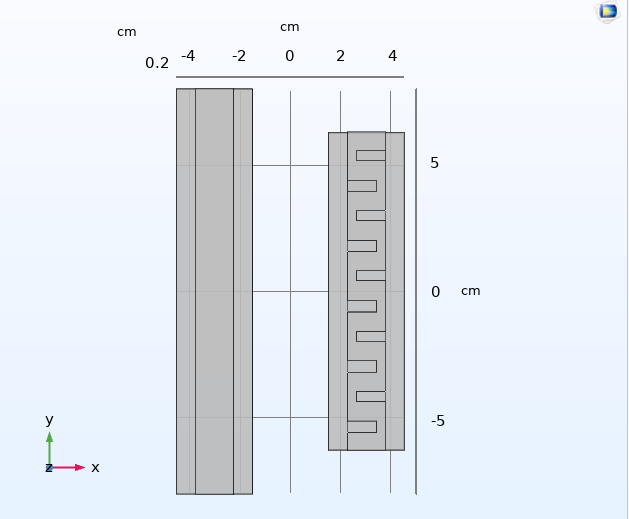
Figure 1: The comparison with regular microstrip (left) and meandered
line microstrip (right).
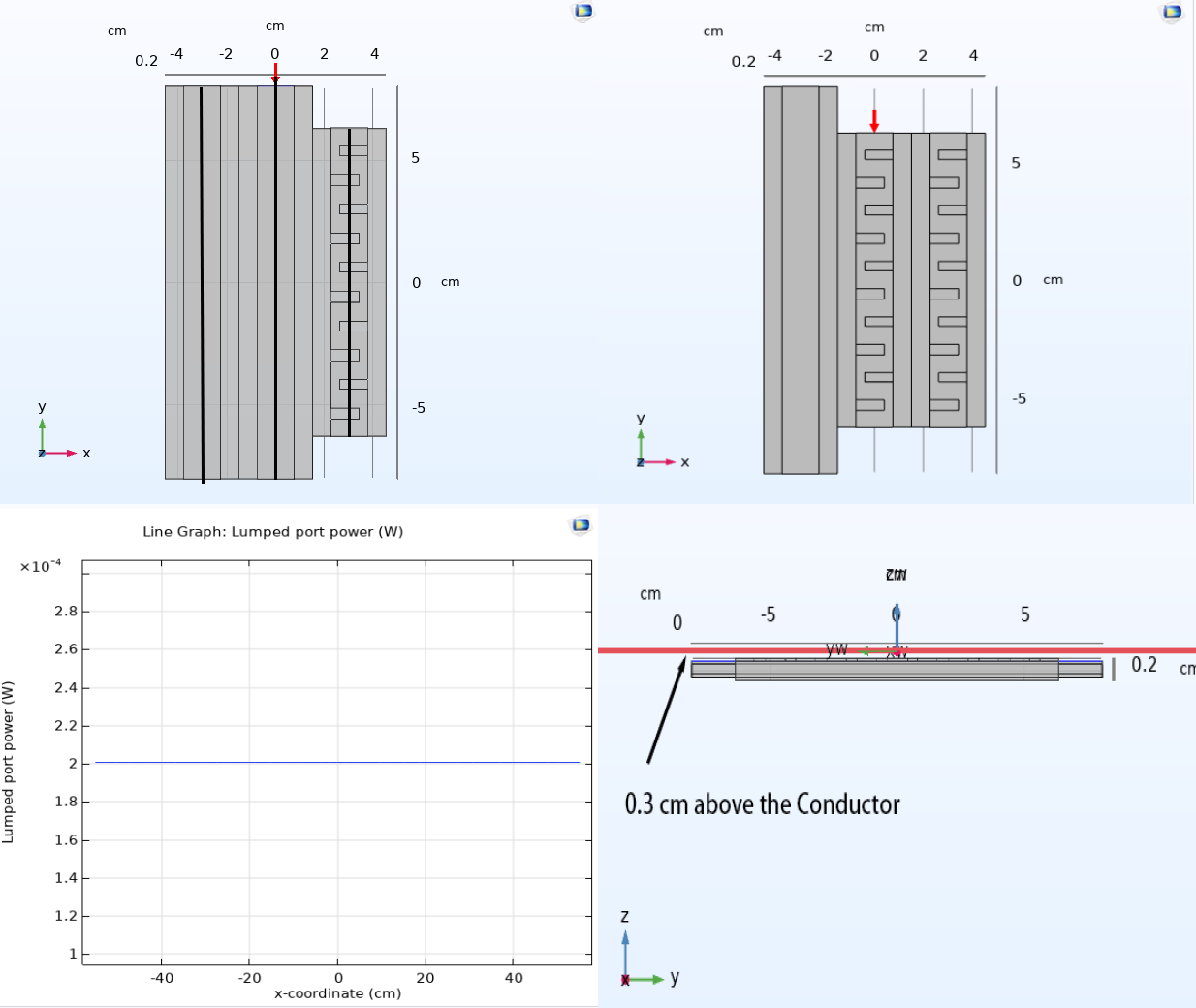
Figure 2: Two experiment setups for decoupling performance test, with red
arrow point at the excitation port with lumped power adjustment and field
measure location.
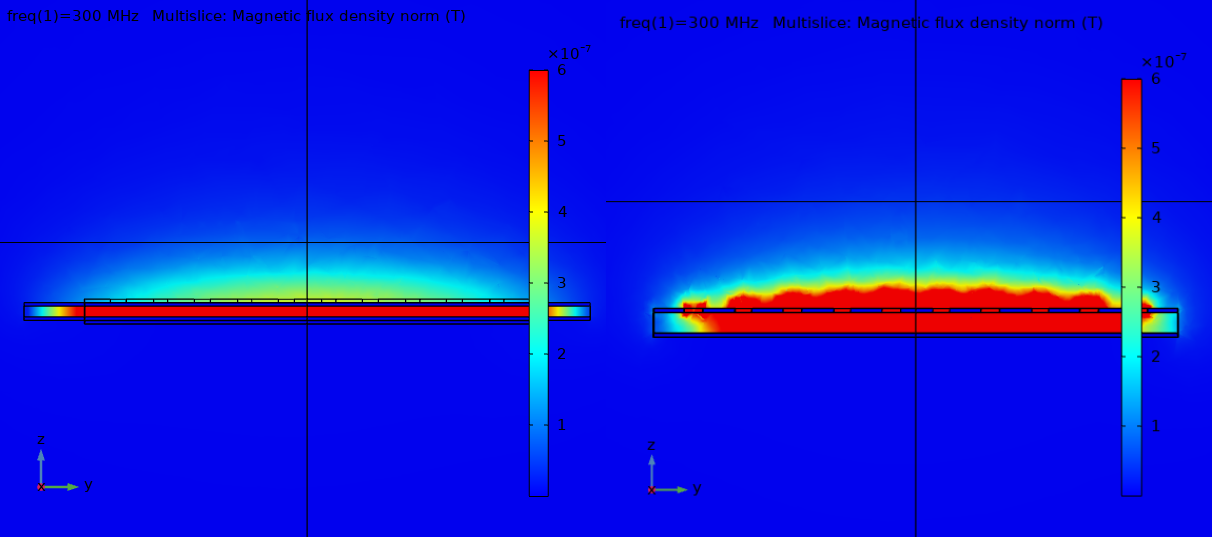
Figure 3: Magnetic field (B field) distribution for two regular
microstrips, one meandered line microstrip, (Left) another with two meandered
line microstrip, and one regular microstrip. (Right)
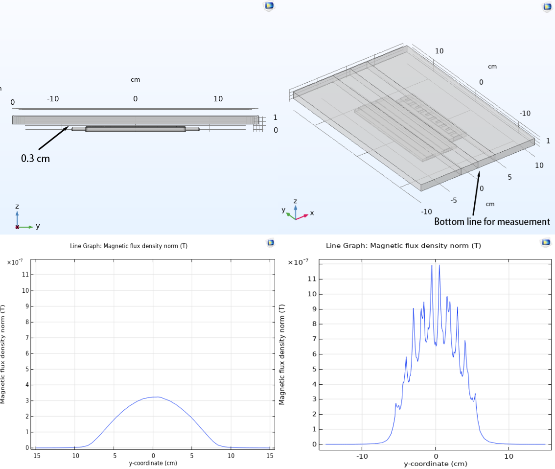
Figure 4: The magnetic flux density for middle
excited microstrip at 0.3 cm above the conductor. The bottom left is for two regular
microstrips, one meandered line microstrip, (Left) another with two meandered
line microstrip, and one regular microstrip. (Right)
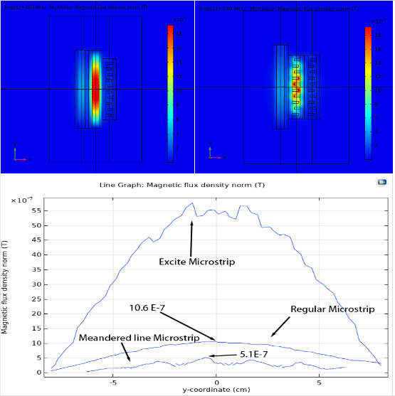
Figure 5: The coupling performance test for middle excited
microstrip at 0.3 cm above the conductor. The bottom left is for two regular
microstrips, one meandered line microstrip, (Left) another with two meandered
line microstrip, and one regular microstrip. (Right)
DOI: https://doi.org/10.58530/2022/4505