4504
Investigation of Magnetic Wall Decoupling for planar Quadrature RF Array coils using Common-Mode Differential-mode Resonators
Komlan Payne1, Salik Inayat Khan1, and Xiaoliang Zhang1
1Jacobs School of Medicine & Biomedical Sciences, University at Buffalo, The State University of New York, Buffalo, NY, United States
1Jacobs School of Medicine & Biomedical Sciences, University at Buffalo, The State University of New York, Buffalo, NY, United States
Synopsis
Parallel imaging using quadrature coil arrays can help to reach their ultimate intrinsic signal-to-noise ratio (uiSNR) and higher spatial resolution at ultra-high fields, because quadrature RF coils provide higher sensitivity and reduced excitation power over the commonly used linear polarized RF transceivers. However, due to the complicated structure and difficulties in achieving sufficient electromagnetic decoupling, it is technically challenging in designing multichannel quadrature RF coil arrays, particularly at ultrahigh fields. In this work, we design and investigate the magnetic wall decoupled common-mode differential mode quadrature RF arrays for ultrahigh field 7T MR imaging applications.
Introduction
Transceiver RF coils with the capability to achieve quadrature or circularly polarized electromagnetic field have demonstrated superior performance over linear polarized field, providing higher signal to noise ratio (SNR) and reduced signal excitation power 1-2. Magnetic resonance imaging (MRI) at ultra-high fields has made progress toward the use of RF coils based on microstrip transmission line (MTL) theory 3. One of the main advantages of MTL over conventional RF coils is coming from its inherent low radiation losses. The well-known common mode differential mode (CMDM) resonator owing to two orthogonal and intrinsically decoupled modes, the common-mode (CM) and differential-mode (DM), was employed for the design of double nuclear 4 and quadrature 5 transceiver. While the CMDM resonator has served as a building block to design a non-array volume coil for double nuclei 1H/13C MR acquisitions due to the enhance coupling between elements 4, no study was reported for the development of multichannel CMDM quadrature transceiver arrays for parallel imaging which conversely benefit from low inter-coupling between elements of the array. In fact, array of CMDM resonators lead to complex coupling between the two existing current modes. In this study, we investigate the capability of using magnetic wall 6 as a non-overlapping decoupling method for CMDM planar quadrature RF array. To verify the proposed approach, a pair of quadrature CMDM resonators is designed with and without the magnetic wall decoupling network and their decoupling performance are evaluated using full wave electromagnetic analysis (HFSS). It has been revealed that the magnetic wall decoupling design adopted can be used to sufficiently suppress either the mutual common mode or differential mode current.Methods
A single quadrature element using CMDM resonator is designed to operate at 300 MHz (the Larmor Frequency of proton 1H at 7T). The CMDM resonator 5 based on split microstrip transmission line is made of 4 mm strip copper thickness and a ground plane separated by a dielectric substrate. The CMDM resonator is placed 2 cm on top of a water phantom. The electric parameters and the physical dimension of the design are depicted in the caption of Fig.1. Numerical analysis reflecting the high intensity quadrature field is illustrated in Fig. 2. A pair of the CMDM resonator separated by 3 cm gap is designed for parallel imaging (see Fig.3). Due to the array configuration, electromagnetic coupling exists not only between the CM-DM but also between CM-CM and DM-DM. In order to mitigate these coupling, a magnetic wall network is placed between adjacent CMDM resonator. A magnetic wall is a resonator implemented with lumped circuit element or distributed element or a mixture of both use to suppress the induced current between the array elements 6. In this study we adopt a microstrip with tunable capacitors at both ends of the transmission line. The pair of quadrature CMDM resonator with the decoupling wall is illustrated in Fig. 4. The effectiveness of the magnetic wall to alleviate the multi-mode coupling between the resonators is investigated and its performance is compared with the pair of CMDM without the decoupling network.Results
The scattering parameters of the single quadrature CMDM resonator in Fig.1 shows that both the CM and the DM are intrinsically decoupled at 7T providing a very low power crosstalk as predicted. This design offers improved constructive transmit RF field ($$$B_1^+$$$) for quadrature excitation as opposed to linear excitation (see Fig.2). The scattering parameter of the pair of quadrature CMDM resonators (Fig. 3) shows that electromagnetic coupling between the two modes exists. Strong coupling is obtained between the CM current (about 37% power cross talk between both resonators) which constitute a major factor that degrade the capability of transmission and detection of the array. However, moderate electromagnetic coupling between the DM current is obtained (about 5 % power cross talk) mainly due to the low capacitance value of C2 and C3 depicted in the caption of Fig. 1. In order to mitigate the coupling between neighboring resonators, the microstrip resonator used as magnetic wall is implemented such that its impedance $$$Z_d$$$ satisfy the equation: $$$Z_d = Z_{dc}^2/Z_{cc}$$$, where $$$Z_{cc}$$$ and $$$Z_{dc}$$$ are the mutual impedance between CMDM1-CMDM2 and magnetic wall-CMDM, respectively. Since two current modes exist in the CMDM resonator we implement the magnetic wall to suppress only the common mode coupling without affecting the differential current path. As can be seen in Fig. 4, the common mode coupling is reduced from -4 dB to -22 dB.Discussion / Conclusion
A pair of transceivers CMDM resonators with quadrature field capability is designed for parallel imaging application. Due to the intricate nature of the coupling between two existing current modes, a microstrip with tuning capacitors at both ends of the transmission line is used to mitigate the inter-coupling between the pair of the CMDM resonators. By evaluating the impedance of this type of magnetic wall, we notice that the MTL can efficiently suppress either the common mode or the differential mode coupling. However, both current modes can’t be sufficiently suppressed concurrently with the current design. Optimization of parameters of magnetic wall decoupling circuits, particularly their impedance, would help to further improve decoupling performance for all resonant modes.Acknowledgements
No acknowledgement found.References
1. G. H. Glover, C. E. Hayes, N. J. Pelc, W. A. Edelstein, O. M. Mueller, H. R. Hart, C. J. Hardy, M. O'Donnell, and W. D. Barber, “Comparison of linear and circular polarization for magnetic resonance imaging”, Journal of Magnetic Resonance (1969), vol. 64, no. 2, pp. 255–270, 1985.2. A. Zailaa, V. Vegh, D. Maillet, and M. W. Strudwick, “Quadrature radio frequency coil for magnetic resonance imaging of the wrist at 4T”, Concepts in Magnetic Resonance Part B: Magnetic Resonance Engineering, vol. 35B, no. 4, pp. 191–197, 2009.
3. Zhang X, Ugurbil K, Chen W. Microstrip RF surface coil design for extremely high-field MRI and spectroscopy. Magn Reson Med 2001; 46:443–50.
4. Pang Y, Zhang X, Xie Z, Wang C, Vigneron DB (2011) Common-mode differential-mode (CMDM) method for double-nuclear MR signal excitation and reception at ultrahigh fields. IEEE Trans Med Imaging 30: 1965-1973. doi:10.1109/TMI.2011.2160192. PubMed: 21693414.
5. Y. Li, B. Yu, Y. Pang, D. B. Vigneron, and X. Zhang, “Planar Quadrature RF Transceiver Design Using Common-Mode Differential-Mode (CMDM) Transmission Line Method for 7T MR Imaging”, PLOS ONE, vol. 8, no. 11, p. e80428, 2013.
6. Y. Li, Z. Xie, Y. Pang, D. Vigneron, and X. Zhang, “ICE decoupling technique for RF coil array designs”, Medical Physics, vol. 38, no. 7, pp. 4086–4093, 2011.
Figures
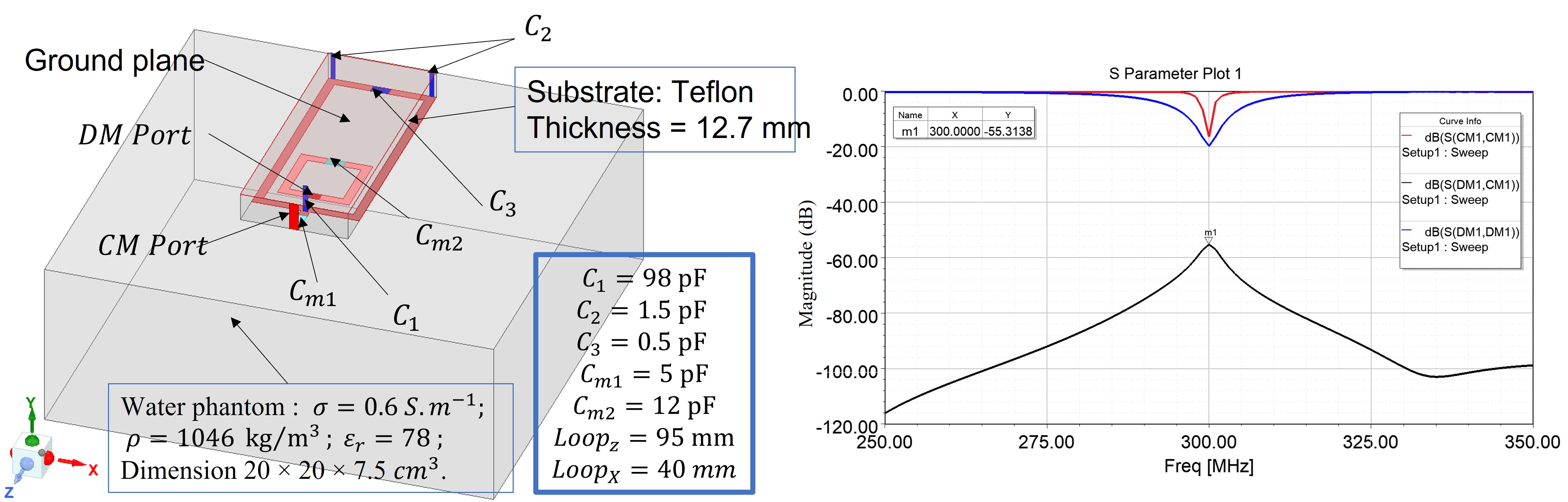
Fig. 1. Topology of quadrature CMDM resonator along with detailed geometry dimension, electrical parameters and simulated scattering parameters.
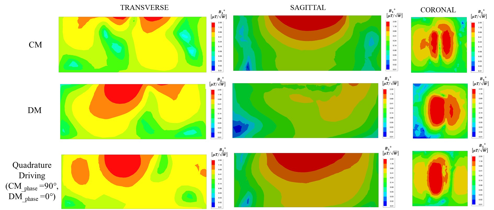
Fig. 2. Simulated transmit $$$B_1^+$$$ field distribution normalized to 1 W of input power in the XY (transversal), YZ (sagittal) plane cutting through the center of the phantom and and XZ (coronal) plane on the top of the phantom.
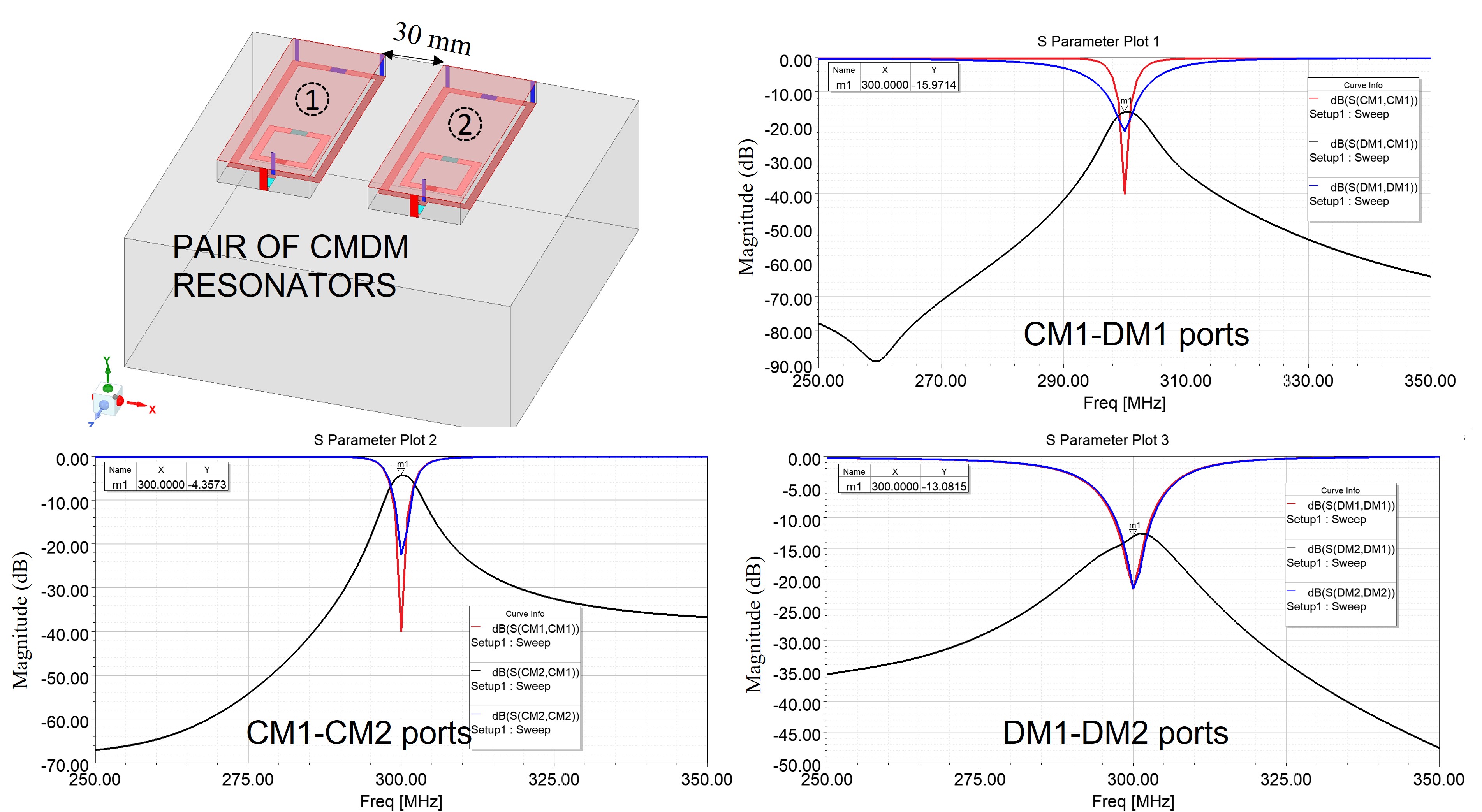
Fig. 3. Pair of quadrature CMDM resonators on top of the phantom separated by 3 cm gap. Simulated frequency response this configuration showing the electromagnetic coupling between the multimode resonators.
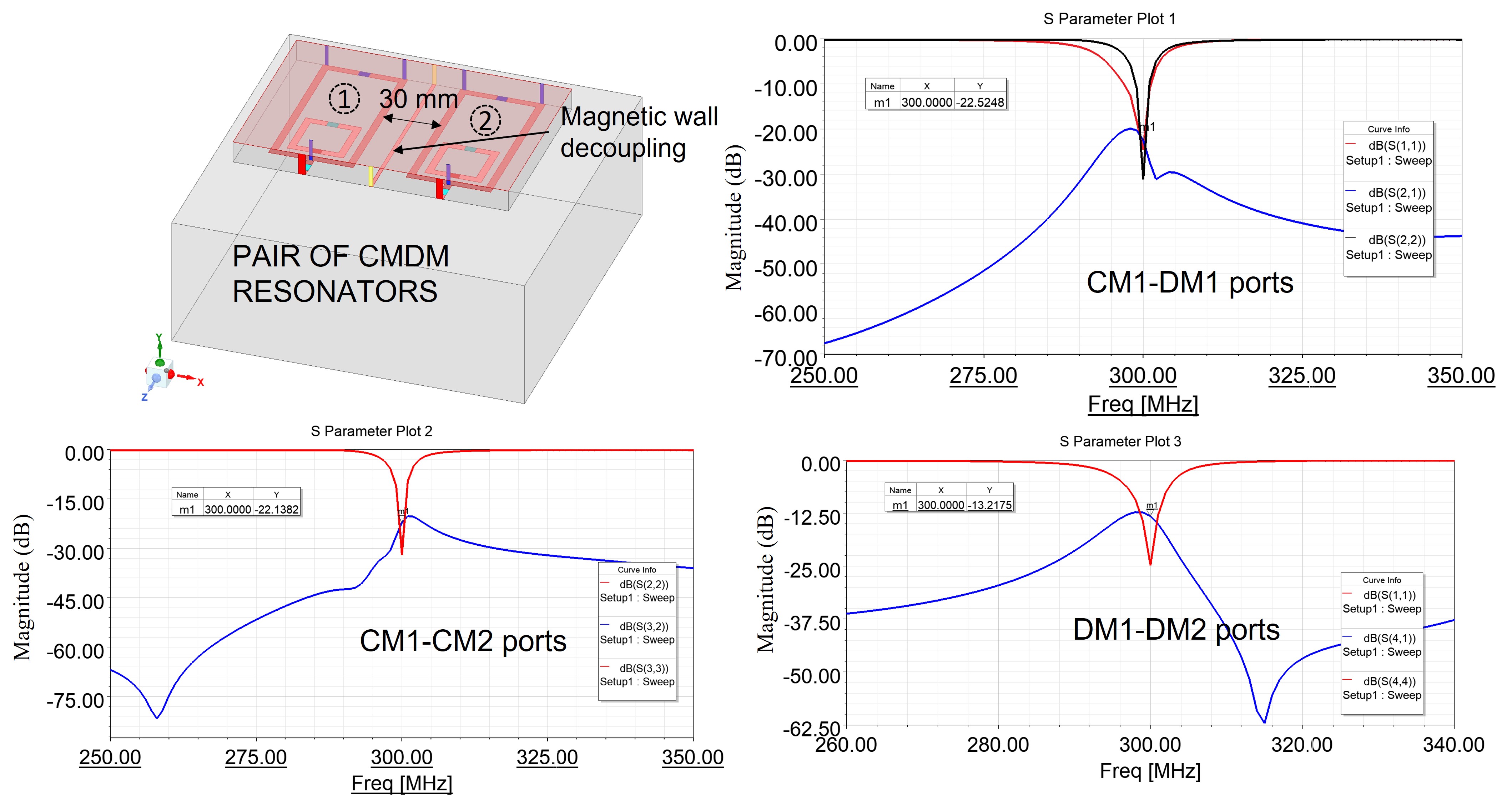
Fig. 4. Pair of quadrature CMDM resonators with the magnetic wall decoupling on top of the phantom. Simulated frequency response this configuration showing the electromagnetic coupling between the multimode resonators.
DOI: https://doi.org/10.58530/2022/4504