4503
Hairpin Radio Frequency Coil Array with High Inter-channel isolation for 7T Magnetic Resonance Imaging
Komlan Payne1 and Xiaoliang Zhang1
1Jacobs School of Medicine & Biomedical Sciences, University at Buffalo, The State University of New York, Buffalo, NY, United States
1Jacobs School of Medicine & Biomedical Sciences, University at Buffalo, The State University of New York, Buffalo, NY, United States
Synopsis
The quest for ultimate intrinsic signal-to-noise ratio (uiSNR) and higher spatial resolution at ultra-high field for parallel magnetic resonance imaging is contingent to the integrity of the magnetic flux density map from individual channel. RF coils design using hair-pin matching technique is introduced to provide intrinsic decoupling performance within array of elements. This technique does not require any additional circuit between coil elements or large value of lumped inductance to provide simultaneous decoupling between adjacent and non-adjacent coils. The simulated results including decoupling performance, field distribution, and SNR are provided to validate the feasibility of the proposed design.
Introduction
Intrinsic decoupling of RF array coils is required to maintain selective magnetic flux density map from individual channel at ultra-high field (UHF) for parallel imaging 1-2. A close-fitting or high-density array for high spatial resolution, leads to strong coupling between elements making the decoupling mechanism a very challenging task at UHF. The “self-decoupled” RF coils 3, a demonstration of high impedance decoupling 4, have demonstrated to be a prominent simple design method to circumvent these coupling issues. However, this decoupling technique come at the expense of the SNR and B1 field efficiency. In fact, the use of lumped inductor with relatively large value of inductance is needed in the high impedance self-decoupled RF coils for sufficient decoupling. Due to their inherently low-quality factor, a significant amount of power is expected to be dissipated within these inductors and not readily to be used for MR imaging, leading to degraded B1 efficiency. Therefore, the self-decoupled coils has the limitation in reaching their ultimate intrinsic signal-to-noise ratio (uiSNR). In this work we propose a hairpin RF coil design technique that provides excellent decoupling performance without the need of lumped inductors in the coil array. The performance of the proposed hairpin coil was evaluated and compared to the self-decoupled coils at 7T using full wave electromagnetic simulation. The MR imaging results within a cylindrical phantom obtained from eight-channel array simulations demonstrated a 13 % increase in SNR field intensity of the hairpin design under the same circumstance.Methods
A pair of the proposed hairpin coils is designed to operate at 298 MHz (Larmor frequency of 7T for proton 1H). As shown in Fig. 1, a small conductor wire is connected across the driven terminal of each coil. The wire can take any shape form (in this case, a U-shape is adopted) and can be viewed as inductance across the feeding of the loop used to adjust the surface impedance of the coil. The two loops are separated from each other with 1 cm gap and wrapped on a 14.5 cm radius virtual cylindrical surface. The coils are placed 2 cm on top a cylindrical phantom (conductivity σ = 0.6 S/m and permittivity εr = 50) to mimic the human brain tissue. The decoupling performance of the proposed design is evaluated against the self-decoupled RF coils as shown in Fig. 2. The lumped capacitors and inductors are models as lossy series resonators with realistic quality factors. The Q-factor of the capacitors is set to 1000 while the inductors is set to 250 from their datasheet. To highlight the upturn in the image quality of the hairpin design over the self-decoupled coils, we evaluate the SNR of an array of 8 channels wrapped around the cylindrical phantom. The arrangement of the array over the phantom for both design is illustrated in Fig. 5. All the 8 elements are excited using lumped ports with 1 W input power and 45° linear phase progression.Results
Numerical results are obtained using full wave electromagnetic analysis (HFSS). Both the pair of hairpin RF coil and the self-decoupled RF coils show excellent input impedance matching, and high isolation between the pair of coils (see Fig.1 & 2). The surface current density and electric field distribution obtained show negligible effect in the passive coil (see Fig.3 & 4) when only one coil is excited, which is characteristic of strong decoupling performance for both designs. The scattering parameter of the 8 channels for both designs also exhibit good matching performance and excellent decoupling performance between all neighboring elements. The simulated SNR maps of the 8 channels array on the cylindrical phantom is calculated using the built-in Fields Calculator module in ANSYS HFSS. For comparison between both designs, we evaluate the relative value of SNR defined as $$$SNR_{90}=SNR/sin\alpha$$$ , where the flip angle $$$\alpha$$$=90°. The simulated RF receive/transmit ($$$B_1^-/B_1^+$$$) field and the $$$SNR_{90}$$$ map on the phantom obtained from the 8 elements arrays is illustrated in Fig. 5. A significant signal boost is obtained for the hairpin RF coils at the peripheral as well as the center of the phantom. The quantitative data shows a gain in an average of 13% increase in SNR intensity for the hairpin coils array.Conclusion
We have proposed and designed novel RF coil arrays using hairpin matching technique with excellent performance in electromagnetic decoupling and B1 efficiency at the UHF of 7-Tesla. The proposed hairpin RF technique, requiring no additional decoupling circuits, provides a simple and robust design solution to multichannel RF arrays for MR imaging applications. Unlike the existing “Self-decoupled” RF coils, the proposed hairpin RF coils do not need any lumped inductors. The study shows that the hairpin RF coil is able to circumvent the significant power loss and B1 degradation of the existing “self-decoupled” RF coils due to their use of the large value lumped inductors. As anticipated, this method demonstrated substantial gain in SNR crucial for improving resolution and parallel imaging performance. Although the technique is examined for 7T it can be scaled to lower field (static magnetic field B0 < 7T) where the system power loss is more pronounced when using the existing self-decoupled RF coils with lumped inductors.Acknowledgements
No acknowledgement found.References
1. Yan, X., Zhang, X., Feng, B., Ma, C., Wei, L., Xue, R., 2014. 7T Transmit/Receive Arrays Using ICE Decoupling for Human Head MR Imaging. IEEE Transactions on Medical Imaging 33, 1781–1787.. doi:10.1109/tmi.2014.23138792. Yan, X., Ole Pedersen, J., Wei, L., Zhang, X., Xue, R., 2015. Multichannel Double-Row Transmission Line Array for Human MR Imaging at Ultrahigh Fields. IEEE Transactions on Biomedical Engineering 62, 1652–1659.. doi:10.1109/tbme.2015.2401976
3. X. Yan, J. C. Gore, and W. A. Grissom, "Self-decoupled radiofrequency coils for magnetic resonance imaging," Nat Commun, vol. 9, no. 1, p. 3481, Aug 28 2018, doi: 10.1038/s41467-018-05585-8.
4. P Roemer, W Edelstein, C Hayes, S Souza, O Mueller. The NMR Phased Array. MRM 16, 192-225 (1990)
Figures
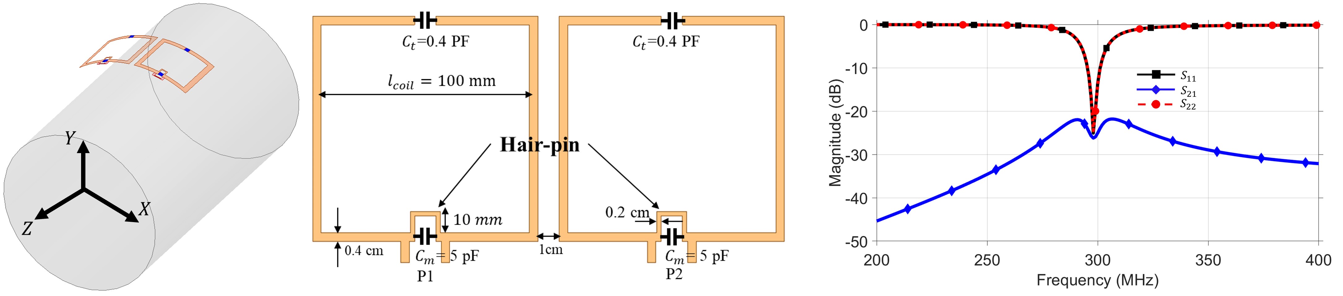
Fig.1 Topology of hair-pin RF coils along with detailed geometry dimension and electrical parameters. Pair of loops on top of a cylindrical phantom. Simulated scattering parameters of the self-decoupled RF coils.
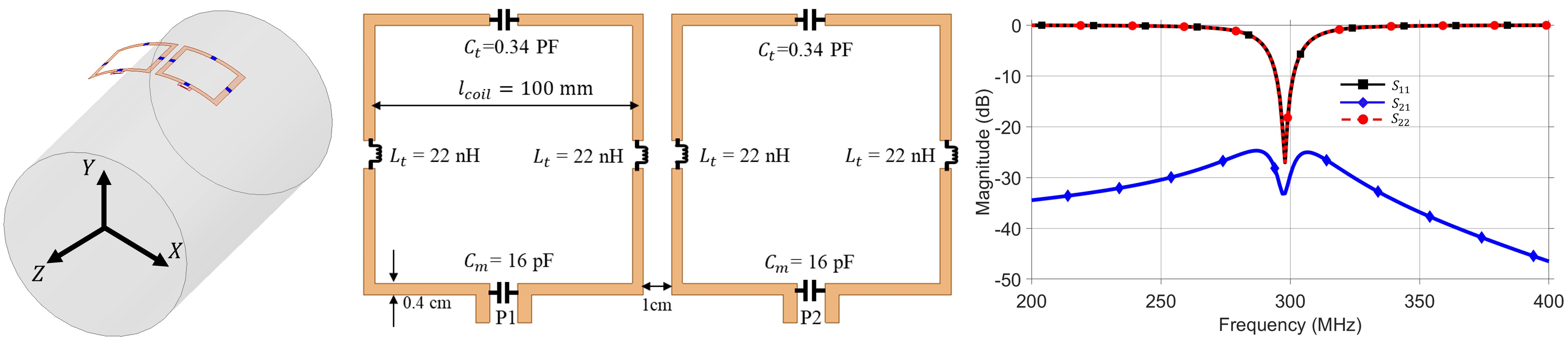
Fig.2 Topology of self-decoupled RF coils along with detailed geometry dimension and electrical parameters. Pair of loops on top of a cylindrical phantom. Simulated scattering parameters of the self-decoupled RF coils.
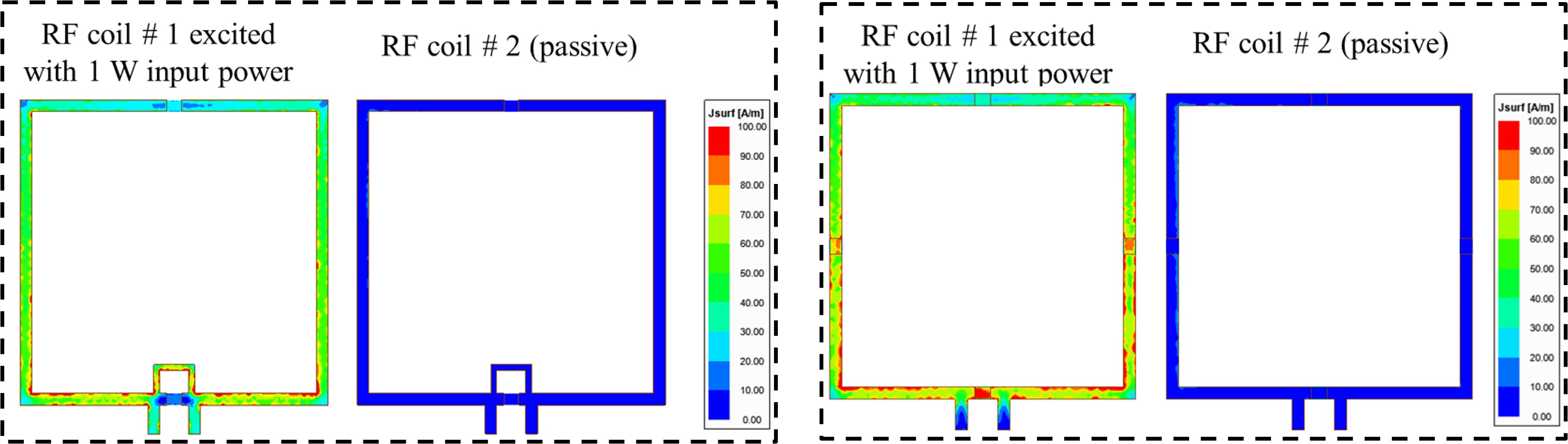
Fig.3 Simulated surface current distribution obtained at 298 MHz for the hair-pin RF coils (left) and the self-decoupled coils (right). Both designs present practically the same current distribution along the conductors of the RF coils.
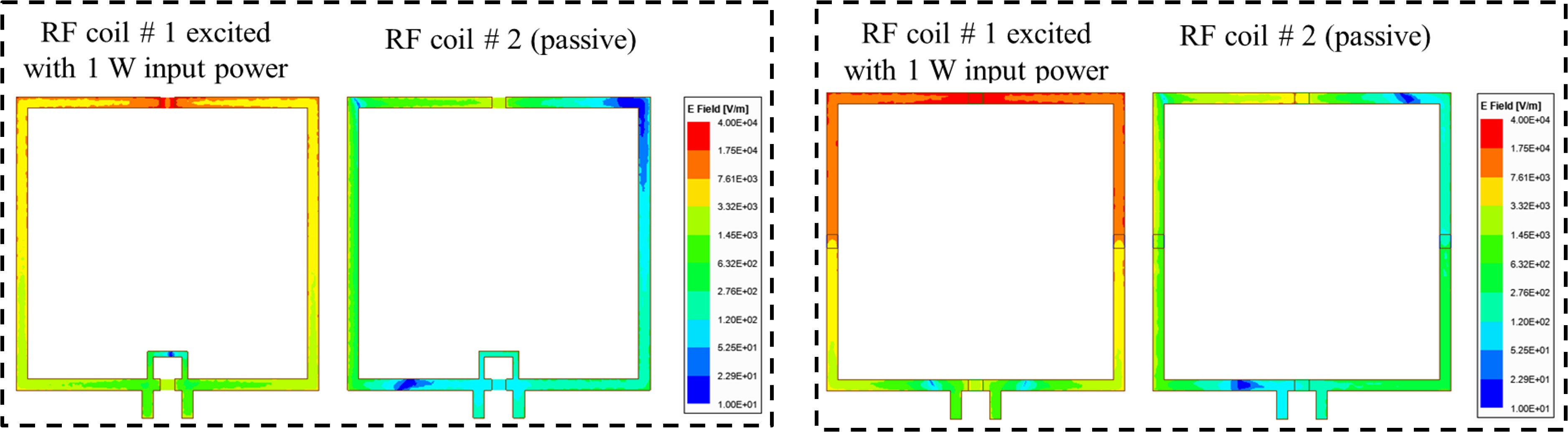
Fig.4 Simulated electric field distribution along the RF coils at 298 MHz for the hair-pin RF coils (left) and the self-decoupled coils (right). Overall, higher electric field amplitude is observed within the self-decoupled coils compared to the hair-pin RF coils.
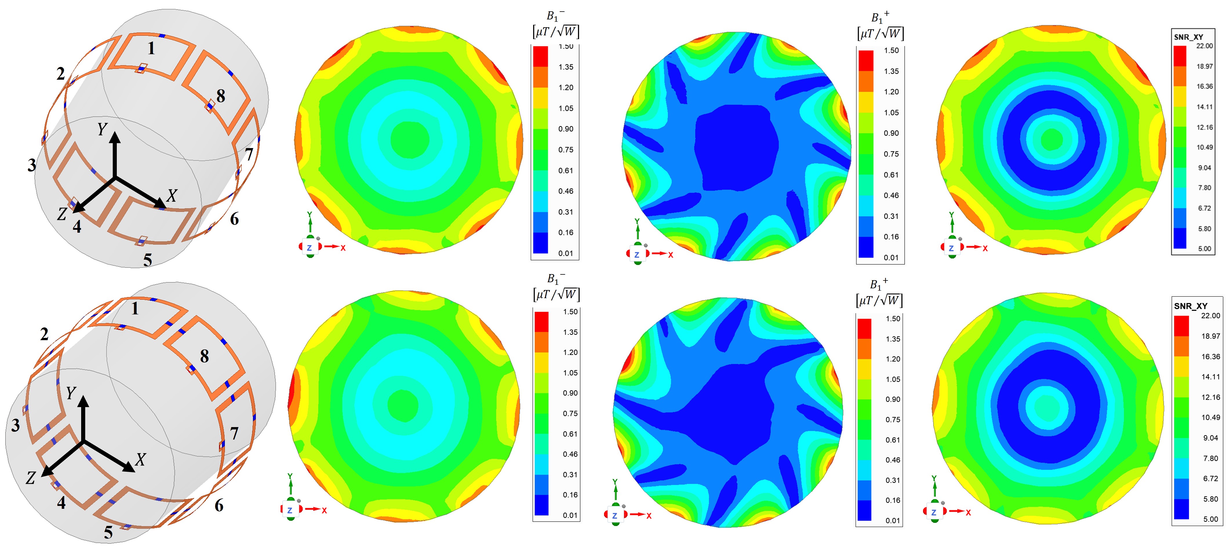
Fig.5 Simulated receive/transmit ($$$B_1^-/B_1^+$$$) field distribution and relative signal-to-noise ratio ($$$SNR_{90}$$$) map on the phantom (transversal plane through the center of the RF coils) obtained from the 8 elements arrays of both design excited with 1 W input power and 45° linear phase progression. The quantitative data shows a gain in an average of 13% in SNR intensity for the hair-pin RF coils.
DOI: https://doi.org/10.58530/2022/4503