4501
Self-shielded and self-decoupled transmit RF array for 7T head imaging1Vanderbilt University Institute of Imaging Science, Nashville, TN, United States, 2Department of Radiology and Radiological Sciences, Vanderbilt University Medical Center, Nashville, TN, United States
Synopsis
Transmit (Tx) array with multiple independent coil elements is a well-recognized approach to addressing the B1 inhomogeneity and high local SAR issues at ultrahigh fields. However, Tx arrays typically have a lighter loading and more severe coil coupling. We designed a self-shielded and self-decoupled 2x8 Tx array with high inter-element isolation for 7T head imaging. Each Tx element is based on the corner-fed self-decoupled coil. Four coil elements were constructed to prove the concept is viable. The coil elements are highly decoupled (inter element response < -15 dB) while maintaining good tuning/matching characteristics (power reflection < -20 dB).
Introduction
Transmit (Tx) array with multiple independent coil elements is a well-recognized approach to addressing the B1 inhomogeneity and high local SAR issues at ultrahigh fields [1]–[14]. Due to the space restriction, Tx arrays are typically placed outside the receive (Rx) array, several centimeters away from the tissue, leading to a lighter loading and more severe coil coupling. At the same time, the standard preamp decoupling in the Rx array is not feasible for Tx coils. Therefore, Tx arrays usually require special decoupling methods that increase the hardware complexity and cost, especially for multi-row Tx arrays with strong coupling from elements in the same rows and columns. Therefore, a simple Tx array design is preferred to simplify hardware fabrication and reduce failure costs and risk. We designed and constructed a self-shielded and self-decoupled 2x8 Tx array with high inter-element isolation for 7T head imaging. Unlike conventional Tx arrays, this coil array is easy to build/reproduce because individual coil blocks could be easily assembled without worrying about coil coupling.Methods
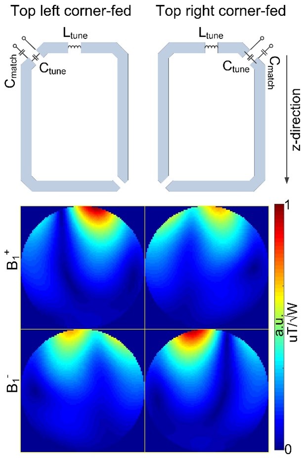
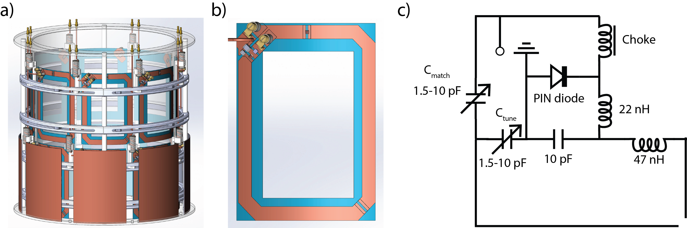
The modular Tx element is based on the corner-fed self-decoupled coil [15]. As currents along the two arm conductors are not equal in magnitude, B1 fields of the coil differ when fed at the top left or top right corner. In this work, the coil was fed at the top-left corner to benefit the B1+ field. Figure 1 shows how the B1+ and B1- changed when the feed board changed from the top left corner to the top right corner.The Tx array was designed to be mounted on a 29-cm-diameter acrylic tube (Figure 2a). Each coil has a length/width of 13/9 cm and was made from 10-mm-width copper tape (Figure 2b). The detailed circuit schematic of each Tx coil is shown in Figure 2c. The frequency tuning and impedance matching were realized by trimmer capacitors (from 1.5 pF to 10 pF) instead of inductors. Each coil was individually shielded to avoid its crosstalk with the outer environment. To realize self-decoupling for both circumferential and axial directions, the coil conductor has a 1.7-mm gap at the centrosymmetric position to the feed port. An active detune circuit was employed to disable the Tx coil during the receive phase. A 2x2 coil array was built and bench-tested on a cuboid phantom placed 5 cm below.
Results and Discussion
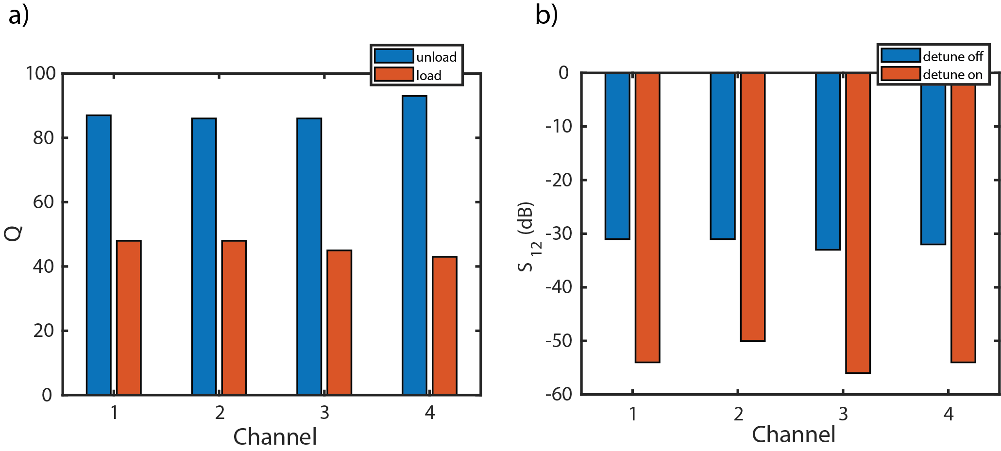
Figure 3a shows the constructed four self-shielded and self-decoupled coils (2x2 layout, with the shield on/off). Figures 3b plotted the measured S-parameters versus frequency, and Figure 3c depicted the S-matrix at the desired frequency (298 MHz, Larmor frequency of 7T). The inter-element isolation between the adjacent element in the same row (S12 and S34), adjacent elements in different rows (S14 and S23), and diagonal elements (S13 and S24) are ~ -18/-18 dB, ~ -24/-15 dB, and ~-24/-15 dB, respectively. Figure 4a shows each coil's measured quality factors (Q-) in both unloaded and loaded scenarios. The measured ratios between unloaded and loaded Q-factors range from 1.79 to 2.16, with an average of 1.92. Figure 4b depicted the detune performance measured with a double-pick-up probe. The detune could achieve <-20 dB for each coil, indicating a neglectable effect on the receive performance when a separate receive array is used.Conclusion
A 16-channel double-row self-shielded and self-decoupled Tx coil array was designed, initially constructed, and tested. The self-decoupling approach eliminates additional decoupling methods, and the individual modular shield eliminates the need for a whole RF shield. This design is easy to build/reproduce, providing a much simpler approach to constructing highly-decoupled multi-row detunable Tx arrays for human imaging at ultrahigh fields.Acknowledgements
This project is supported by NIH EB R21 029639.References
[1] Y. Zhu, “Parallel excitation with an array of transmit coils,” Magn. Reson. Med., vol. 51, no. 4, pp. 775–784, 2004, doi: 10.1002/mrm.20011.
[2] W. Grissom, C. Yip, Z. Zhang, V. A. Stenger, J. A. Fessler, and D. C. Noll, “Spatial domain method for the design of RF pulses in multicoil parallel excitation,” Magn. Reson. Med., vol. 56, no. 3, pp. 620–629, 2006, doi: 10.1002/mrm.20978.
[3] U. Katscher, P. Börnert, C. Leussler, and J. S. van den Brink, “Transmit SENSE,” Magn. Reson. Med., vol. 49, no. 1, pp. 144–150, 2003, doi: 10.1002/mrm.10353.
[4] B. Guérin et al., “Comparison of simulated parallel transmit body arrays at 3 T using excitation uniformity, global SAR, local SAR, and power efficiency metrics,” Magn. Reson. Med., vol. 73, no. 3, pp. 1137–1150, 2015, doi: 10.1002/mrm.25243.
[5] B. Guérin, M. Gebhardt, S. Cauley, E. Adalsteinsson, and L. L. Wald, “Local specific absorption rate (SAR), global SAR, transmitter power, and excitation accuracy trade-offs in low flip-angle parallel transmit pulse design,” Magn. Reson. Med., vol. 71, no. 4, pp. 1446–1457, 2014, doi: 10.1002/mrm.24800.
[6] G. Adriany et al., “Transmit and receive transmission line arrays for 7 Tesla parallel imaging,” Magn. Reson. Med., vol. 53, no. 2, pp. 434–445, 2005, doi: 10.1002/mrm.20321.
[7] V. Alagappan et al., “Degenerate mode band-pass birdcage coil for accelerated parallel excitation,” Magn. Reson. Med., vol. 57, no. 6, pp. 1148–1158, 2007, doi: 10.1002/mrm.21247.
[8] G. Adriany et al., “A geometrically adjustable 16-channel transmit/receive transmission line array for improved RF efficiency and parallel imaging performance at 7 Tesla,” Magn. Reson. Med., vol. 59, no. 3, pp. 590–597, 2008, doi: 10.1002/mrm.21488.
[9] N. I. Avdievich, “Transceiver-Phased Arrays for Human Brain Studies at 7 T,” Appl. Magn. Reson., vol. 41, no. 2, pp. 483–506, Dec. 2011, doi: 10.1007/s00723-011-0280-y.
[10] B. Wu et al., “Multi-Channel Microstrip Transceiver Arrays Using Harmonics for High Field MR Imaging in Humans,” IEEE Trans. Med. Imaging, vol. 31, no. 2, pp. 183–191, Feb. 2012, doi: 10.1109/TMI.2011.2166273.
[11] O. Kraff et al., “An Eight-Channel Phased Array RF Coil for Spine MR Imaging at 7 T,” Invest. Radiol., vol. 44, no. 11, pp. 734–740, Nov. 2009, doi: 10.1097/RLI.0b013e3181b24ab7.
[12] B. Wu et al., “7T Human Spine Imaging Arrays With Adjustable Inductive Decoupling,” IEEE Trans. Biomed. Eng., vol. 57, no. 2, pp. 397–403, Feb. 2010, doi: 10.1109/TBME.2009.2030170.
[13] A. J. E. Raaijmakers et al., “Design of a radiative surface coil array element at 7 T: The single-side adapted dipole antenna,” Magn. Reson. Med., vol. 66, no. 5, pp. 1488–1497, 2011, doi: 10.1002/mrm.22886.
[14] C. Thalhammer et al., “Two-Dimensional sixteen channel transmit/receive coil array for cardiac MRI at 7.0 T: Design, evaluation, and application,” J. Magn. Reson. Imaging, vol. 36, no. 4, pp. 847–857, 2012, doi: 10.1002/jmri.23724.
[15] X. Yan, J. C. Gore, and W. A. Grissom, “Self-decoupled radiofrequency coils for magnetic resonance imaging,” Nat. Commun., vol. 9, no. 1, p. 3481, Aug. 2018, doi: 10.1038/s41467-018-05585-8.
Figures