4500
A detunable multi-row self-decoupled Transmit Array for 7 T ASL and brain spinal cord Imaging1Vanderbilt University Institute of Imaging Science, Nashville, TN, United States, 2Department of Radiology and Radiological Sciences, Vanderbilt University Medical Center, Nashville, TN, United States
Synopsis
Transmit arrays improves the transmit field homogeneity while reducing the local hot spot. Current array designs for the head are not optimized for arterial spin labeling and simultaneous brain and cervical spinal cord applications caused by the short longitudinal coverage. To approach this problem, we designed and constructed a three-row Tx array covering the whole brain and cervical spinal cords (length: 28 cm). The overall performance of the coil is good with return losses < -20 dB while having adjacent coils’ coupling averaging -25.3 dB and diagonal coil’s coupling averaging -14.6 dB. The coil’s detune circuit also worked as intended.
Introduction
Transmit (Tx) arrays with multiple coil elements have been widely used in ultrahigh field MRI to alleviate the transmit field (B1+) inhomogeneity and reduce specific absorption rate (SAR). Most transmit arrays are focused on brain imaging [1]–[9], and only a few studies investigated transmit coils covering the cerebellum or neck [10], [11]. When toward arterial spin labeling (ASL) and simultaneous brain and cervical spinal cord applications [12], [13], such transmit arrays have relatively poor RF shimming and/or parallel transmission capability owing to the short longitude coverage and the limited number of rows. In this work, we designed and constructed a multi-row Tx array with sufficient longitudinal length to cover the whole brain and cervical spinal cords to overcome this problem. It has a dedicated row of coils to enable the separate control of the B1+ and SAR at the labeling and neck areas.Methods
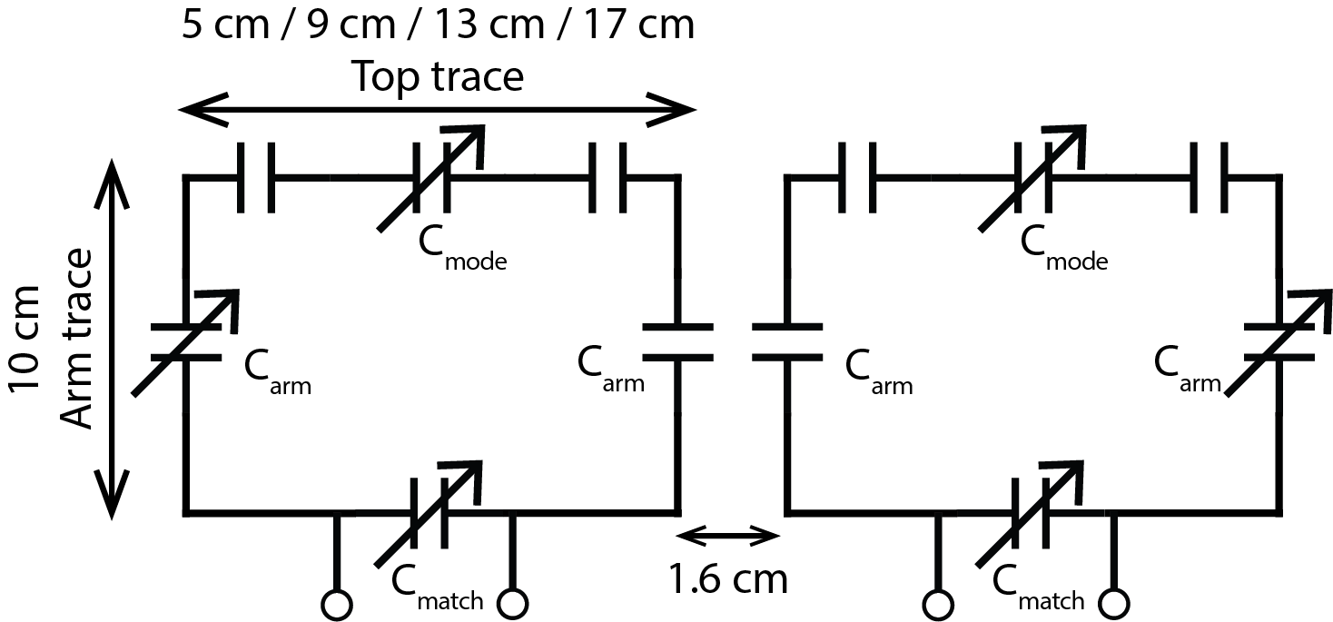
Initial comparison of the self-decoupled coil dimensionsPrior to building the whole array, we first investigated how the decoupling performance changes with coil dimensions. Four pairs of self-decoupled coils with different dimensions (fixed-length 10 cm, width: 5 cm, 9 cm, 13 cm, and 17 cm) were built for comparison. A trimmer capacitor and two 3-pF capacitors were used as Cmode to balance the magnetic coupling and electric coupling mode for decoupling (Figure 1). Each coil was tuned and matched with trimmer capacitors Carm and Cmatch. These trimmers were manually adjusted to minimize the inter-element isolation and maintain excellent impedance matching for all coils. The best achievable S21, S11 and S22 were recorded for each pair of coils, with a cuboid phantom placed 5 cm below the loading (dimension 38 x 30.5 x 21.5 cm3, σ = 0.6 S/m, εr = 78).
Construction of a 16-ch TX Array with semi-flexible self-decoupled coils
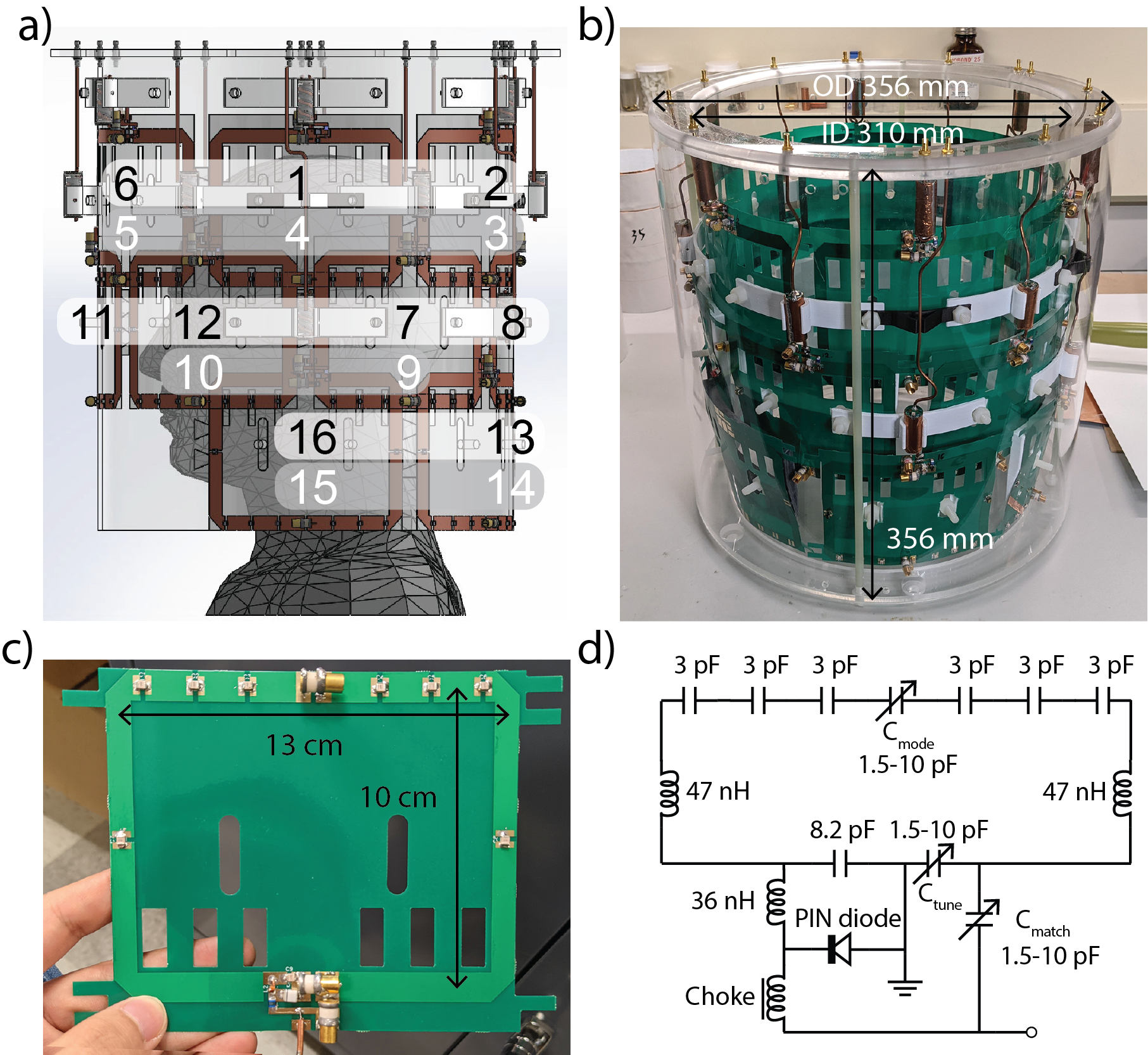
A volume-type TX array was designed in Solidworks (Dassault Systèmes) and constructed on a 29-cm-diameter acrylic tube (Figures 2a and 2b). The loop coils were gapped in the same row and overlapped between adjacent rows. The loop dimension and layout were chosen based on the geometry properties determined in the previous stage and the anatomical size of the brain and cervical spine. This Tx array was arranged in three rows, with six coils in the first and second rows and four in the third row. As shown in Figure 2c, each coil has a length of 10 cm (longitudinal direction) and a width of 13 cm (circumferential direction). This design results in a total longitudinal length of 28 cm, which covers most of the c-spinal cords and the whole brain. Each coil has an active detune circuit to allow a separate close-fitting array for receive, shown in Figure 2d. A shielded cable trap (length 32 mm, diameter 12.7 mm) was employed to reduce the common-mode current. Scattering (S-) parameters of the 16-ch array were measured with a four-port calibrated VNA (Keysight 5071C). Detune of each coil was also measured with a double pick-up probe.
Results and Discussion
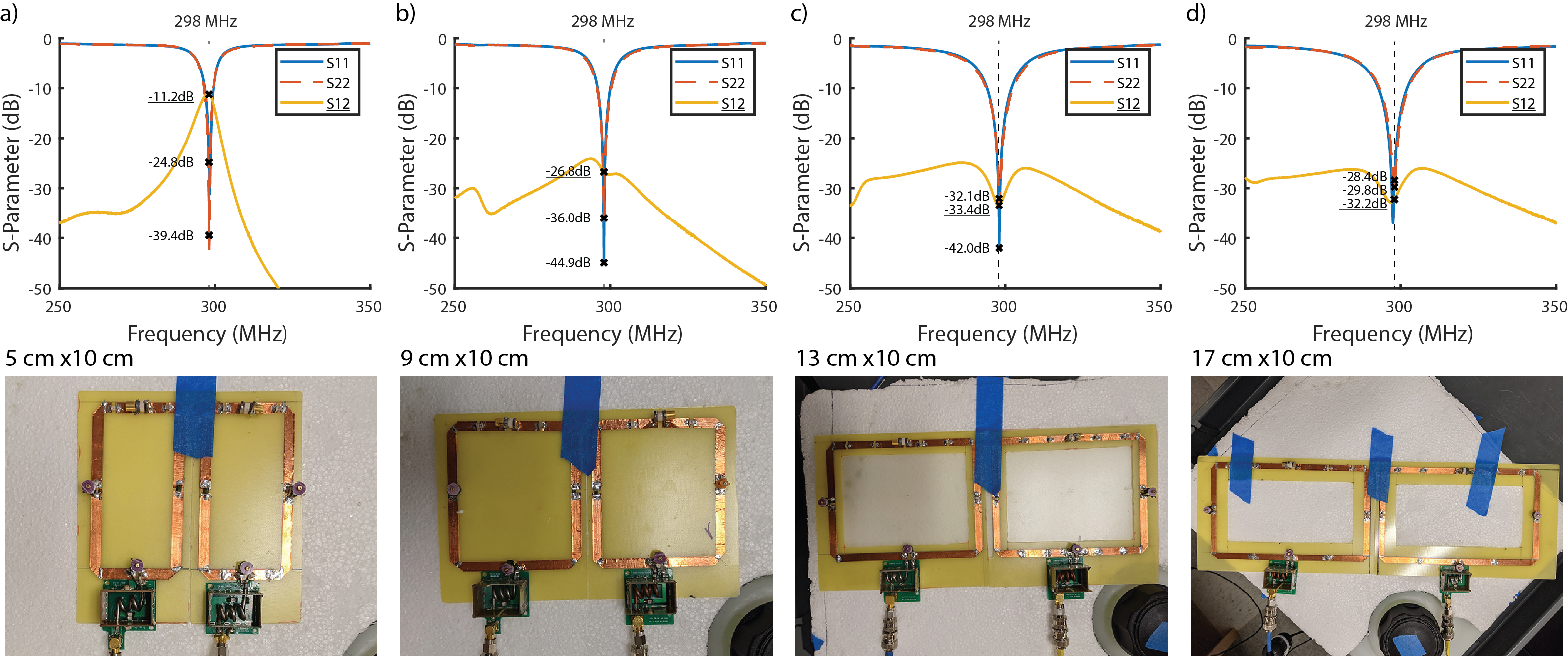
Bench test results of different-sized self-decoupled coilsFigure 4 compared the decoupling performance of different-sized self-decoupled coils. The decoupling ability increases as the coil width increases. When the width is 5 cm, the coil isolation can only achieve 11.2 dB. The relatively poor isolation could be attributed to the fact that the fed conductor cannot generate a sufficient electrical coupling to cancel the magnetic coupling if it is too short, consistent with the simulation results in Lu et al. [14]. The coil isolation increases to 26.8 dB when the width is 9 cm and stabilizes around 33 dB when the width is longer than 13 cm. A 13 cm coil width is decided to be used based on the initial tests and physical limitations.
16-ch TX array
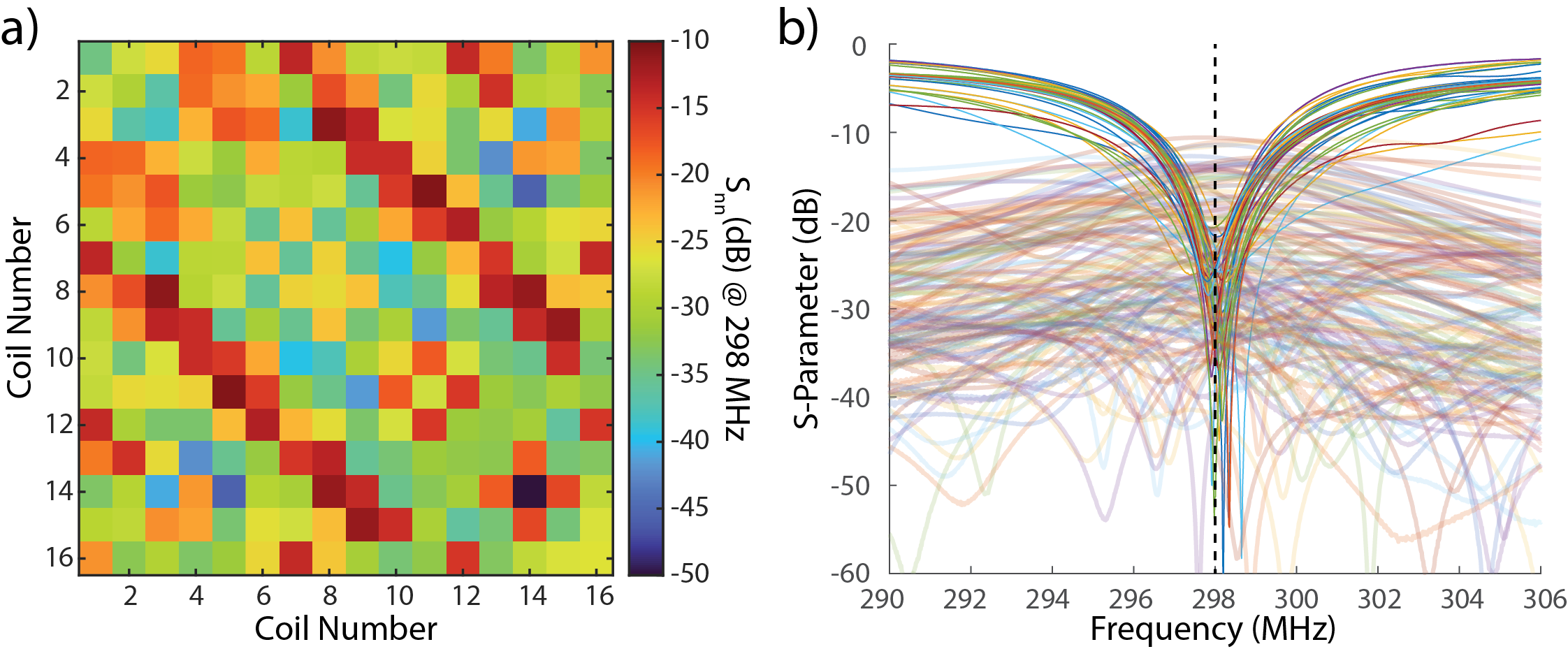
Figure 4a plots measured S-parameters for the constructed 16-ch Tx array, and Figure 4b shows the S-parameter matrix. These S-parameters were measured with a head-shaped phantom positioned at the center of the coil. All coil could be well-tuned to 298 MHz and well-matched to 50 ohms, with Snn<-20 dB (<1% return loss). The average coil isolations between same-row adjacent and diagonal elements are -25.3 dB and -14.6 dB, respectively. The unloaded Q-factors of each coil ranges from 58 to 75, with an average of 66. When loaded with a head-shaped phantom, the Q-factors drop to 33 ~ 39, with an average of 35. For most coils, the Q-ratio is >2, indicating that sample losses are dominant even though coils are several centimeters away from the loading.
Conclusion
We have successfully designed and constructed a multi-row TX array with extended longitudinal coverage to suit ASL and brain + spine applications. It has a separate row of Tx coils for the cervical spine area, bringing more freedom to control transmit field and SAR in the ASL labeling area and cervical spinal cords. This Tx array is also detunable, allowing separate receive arrays to maximize the SNR and parallel imaging performance. Further studies are needed to investigate the Tx performance of this array on ASL and brain + spinal cord imaging.Acknowledgements
This project is supported by NIH EB R21 029639.References
[1] G. Adriany et al., “Transmit and receive transmission line arrays for 7 Tesla parallel imaging,” Magnetic Resonance in Medicine, vol. 53, no. 2, pp. 434–445, 2005, doi: 10.1002/mrm.20321.
[2] X. Zhang, K. Ugurbil, R. Sainati, and W. Chen, “An inverted-microstrip resonator for human head proton MR imaging at 7 tesla,” IEEE Transactions on Biomedical Engineering, vol. 52, no. 3, pp. 495–504, Mar. 2005, doi: 10.1109/TBME.2004.842968.
[3] G. C. Wiggins, A. Potthast, C. Triantafyllou, C. J. Wiggins, and L. L. Wald, “Eight-channel phased array coil and detunable TEM volume coil for 7 T brain imaging,” Magnetic Resonance in Medicine, vol. 54, no. 1, pp. 235–240, 2005, doi: 10.1002/mrm.20547.
[4] B. Wu et al., “Shielded Microstrip Array for 7T Human MR Imaging,” IEEE Transactions on Medical Imaging, vol. 29, no. 1, pp. 179–184, Jan. 2010, doi: 10.1109/TMI.2009.2033597.
[5] X. Yan, X. Zhang, B. Feng, C. Ma, L. Wei, and R. Xue, “7T Transmit/Receive Arrays Using ICE Decoupling for Human Head MR Imaging,” IEEE Transactions on Medical Imaging, vol. 33, no. 9, pp. 1781–1787, Sep. 2014, doi: 10.1109/TMI.2014.2313879.
[6] S.-M. Hong, J. H. Park, M.-K. Woo, Y.-B. Kim, and Z.-H. Cho, “New design concept of monopole antenna array for UHF 7T MRI,” Magnetic Resonance in Medicine, vol. 71, no. 5, pp. 1944–1952, 2014, doi: 10.1002/mrm.24844.
[7] G. Chen, B. Zhang, M. A. Cloos, D. K. Sodickson, and G. C. Wiggins, “A highly decoupled transmit–receive array design with triangular elements at 7T,” Magnetic Resonance in Medicine, vol. 80, no. 5, pp. 2267–2274, 2018, doi: 10.1002/mrm.27186.
[8] X. Yan, L. Wei, R. Xue, and X. Zhang, “Hybrid Monopole/Loop Coil Array for Human Head MR Imaging at 7 T,” Appl Magn Reson, vol. 46, no. 5, pp. 541–550, May 2015, doi: 10.1007/s00723-015-0656-5.
[9] S. Sengupta et al., “A Specialized Multi-Transmit Head Coil for High Resolution fMRI of the Human Visual Cortex at 7T,” PLOS ONE, vol. 11, no. 12, p. e0165418, Dec. 2016, doi: 10.1371/journal.pone.0165418.
[10] X. Yan, J. Ole Pedersen, L. Wei, X. Zhang, and R. Xue, “Multichannel Double-Row Transmission Line Array for Human MR Imaging at Ultrahigh Fields,” IEEE Transactions on Biomedical Engineering, vol. 62, no. 6, pp. 1652–1659, Jun. 2015, doi: 10.1109/TBME.2015.2401976.
[11] J. D. Clément, R. Gruetter, and Ö. Ipek, “A human cerebral and cerebellar 8-channel transceive RF dipole coil array at 7T,” Magnetic Resonance in Medicine, vol. 81, no. 2, pp. 1447–1458, 2019, doi: 10.1002/mrm.27476.
[12] D. S. Williams, J. A. Detre, J. S. Leigh, and A. P. Koretsky, “Magnetic resonance imaging of perfusion using spin inversion of arterial water,” PNAS, vol. 89, no. 1, pp. 212–216, Jan. 1992, doi: 10.1073/pnas.89.1.212.
[13] G. J. Nijeholt et al., “Brain and spinal cord abnormalities in multiple sclerosis. Correlation between MRI parameters, clinical subtypes and symptoms.,” Brain, vol. 121, no. 4, pp. 687–697, Apr. 1998, doi: 10.1093/brain/121.4.687.
[14] M. Lu, J. Gore, X. Yan “Optimization of a massive-element self-decoupled transmit array for 7T head imaging” In ISMRM 2021, abstract # 1421
Figures