4498
A 32-Ch Over-Overlapped Semi-Flexible RF Head Coil Array with Improved Deep Brain SNR1MRI Research Center, Department of Psychiatry, Columbia University, New York, NY, United States, 2New York State Psychiatric Institute, New York, NY, United States, 3Zuckerman Institute, Columbia University, New York, NY, United States
Synopsis
To improve the SNR in deep brain of human head images acquired using RF coil arrays with high coil element count, we proposed a 32-ch coil array with enlarged and over-overlapped coil loop elements laid out on a semi-flexible 3D-printed coil former. The experiment results showed that both the overall homogeneity of images and the SNR in deep brain are significantly improved.
Introduction
The SNR of peripheral brain images has been tremendously improved since the adoption of coil arrays with 32, 64, and 128 elements [1-4]. The SNR in deep brain regions, however, has hardly benefited from the increase of coil elements. For example, the central SNR of a 32-ch head array is about 25% of the peripheral SNR only [2] and remains as low while the peripheral SNR additionally increased by 80% when the element count increased from 32 to 64 [3]. This is due to the rapid sensitivity attenuation of coil elements over distance and relatively high distance between the coil elements and head surface. Indeed, the penetration depth of the sensitivity of a circular loop element, the distance at which the sensitivity drops to 1/e (37%), is comparable to the radius of the coil loop [5, 6]. Moreover, at the distance of the loop diameter, the sensitivity further drops to ~10% only. Thus, the most effective way to improve central sensitivity is to enlarge coil elements and shorten the distance between coil and head. Unfortunately, with the increase of element count of head array, the coil loops must be substantially downsized to satisfy the critical overlap required for optimal decoupling. Furthermore, most head coil arrays in use are rigid so the distance between coil and head is not adjustable.We presented a 32-ch head array to address the issue.
Materials and Methods
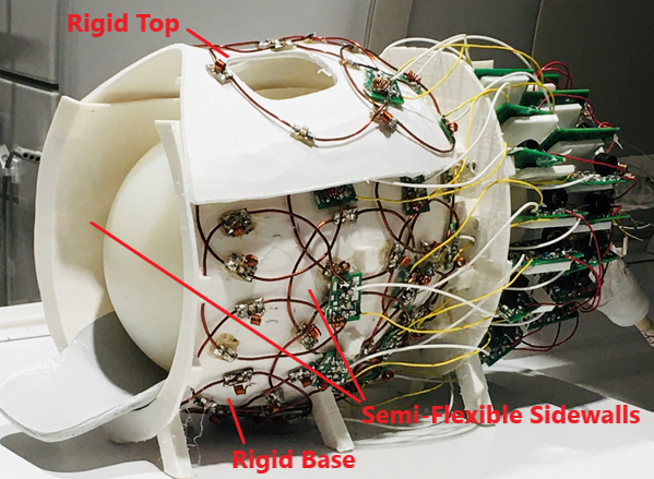
We first developed a 3D printed semi-flexible coil former to fit for different head sizes closely, reducing the distance between coil elements and head to ~5mm and, thereby, maximizing the effective sensitivity [7]. We then enlarged the size of coil elements to extend sensitivity penetration depth to the maximal extent.Our coil former consisted of two parts: the lower part had a rigid base (PLA filament) for support and semi-flexible sidewalls (TPU filament) for size adjusting; the upper part was rigid (PLA) with two cuts for eye view. The two parts were attached by strong Velcro bindings and detachable. When the upper part was lifted/lowered, it pulled/pushed the semi-flexible sidewalls of the lower part outwards/inwards, extending/shrinking both the inner height and width of the coil array. Thus, the inner dimensions could be adjusted from 180mm x 220mm to 220mm x 260mm in horizontal and vertical directions respectively to fit for almost all adult subjects, offering great potentials for optimizing filling factor for various head size while maintaining desirable comfort and safety.
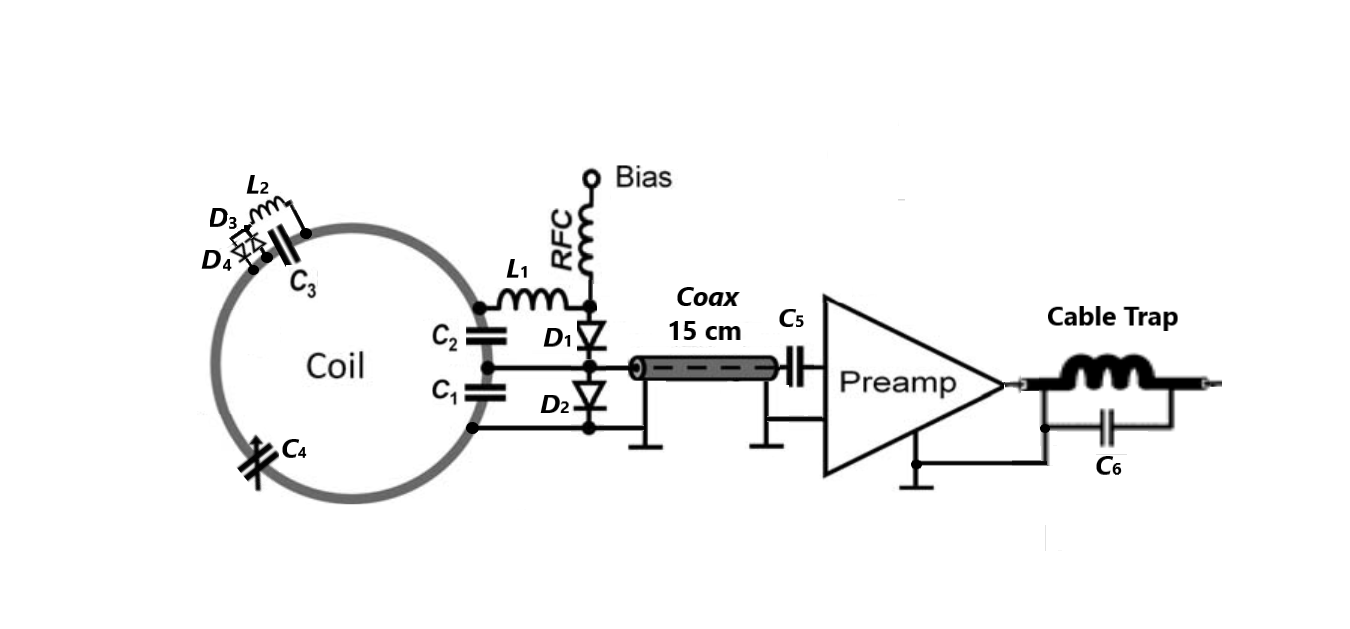
The coil elements were 14-AWG enameled copper wire loops laid out in three rows on lower part with 9 loops in each row and two rows on upper part with 2 and 3 loops on each row respectively [Figure 1]. Each loop was connected by four capacitors (C1-C4) and leaded to a low input impedance preamplifier with a 15mm coax which functioned as an equivalent inductor for preamplifier-based decoupling. Each loop was actively detuned by bias pulse with a trap circuit formed by C2, D2, and L1 and passively detuned with C3, D3, D4 and L2 during RF transmission. A cable trap was built at the output of the preamplifier to choke surface current (Figure 2). With traditional layouts on such a coil former, the diameters of the coil loops would be 70-75mm to maintain the critical overlap (~20% of loop diameter) for optimal decoupling. In this case, however, we increased the loop diameters to 95-100 mm with overlap distances up to ~45% of loop diameters (over-overlapped). To mitigate the coupling resulted from the over-overlapped loops, we employed preamplifiers with ultralow input impedance (0.1-0.5 ohms) and our experiment showed that the degeneration of SNR was less than 3% compared with traditional layouts.
Results and Discussion
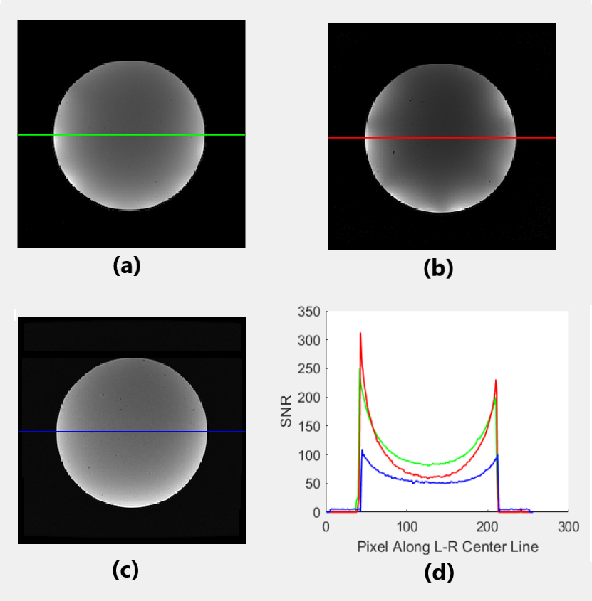
We acquired axial images from a spherical agar phantom having a diameter of 180mm in a 3T MRI scanner (GE Premier) using a T1-MPRAGE pulse sequence (TR=2546.2ms, TE=3.1ms, Flip Angle=8, FOV=256x256mm2, Slice Thickness=1mm, TI=1060ms, NEX=1, BW=31.3kHz, Matrix=256x256).To compare the performance of our coil array with that of commercial coils with similar dimensions, we set the inner dimensions to 185mm x 230mm in similarity to a Nova 32-ch head coil array available in our lab, which was commonly used for cortex study due to its high SNR in peripheral brain benefited from its super close-fitting dimensions. We found that, although the very peripheral SNR of our coil array degenerated by about 20%, the central SNR increased by about 30% and the overall homogeneity was significantly improved (green line in Figure 3a, 3d) compared with the images from the Nova array (red line in Figure 3b, 3d).
In addition, we compared the performance of our coil array with that of GE 48-ch head coil array in larger dimensions (220mm x 260mm) and found that, although the homogeneity of images from GE array (blue line in Figure 3c, 3d) was superior, the overall SNR of our array was about 60% higher.
Conclusions
Our 32-ch array with enlarged loop elements laid out on a semi-flexible coil former showed great potentials for improving the SNR and homogeneity of whole brain images. The ultralow input impedance preamplifiers functioned well in decoupling among over-overlapped coil elements. Human subject imaging will be presented in future work.Acknowledgements
NoneReferences
1. Roemer PB, et al. The NMR phased array. Magn Reson Med. 16:192-25(1990).
2. G.C. Wiggins, et al. 32-Channel 3 Tesla Receive-Only Phased-Array Head Coil With Soccer-Ball Element Geometry. Magnetic Resonance in Medicine 56:216–223 (2006)
3. Kamil Uğurbil, et al. Brain imaging with improved acceleration and SNR at 7 Tesla obtained with 64‐channel receive array. Magn Reson Med. 82:495–509 (2019)
4. Bernhard Gruber, et al. A 128-Channel head coil array for Cortical Imaging at 7 Tesla. ISMRM Annual Meeting, 2021
5. Giulio Giovannetti. Sensitivity estimation in circular and square loops. Concepts Magn Reson Part A. 2019;47A:e21461
6. G. Solomakha, et al. A self-matched leaky-wave antenna for ultrahigh-field magnetic resonance imaging with low specific absorption rate, Nature Communications. https://doi.org/10.1038/s41467-020-20708-w
7. Yunsuo Duan, et al. A Continuously Adjustable 32-Ch Head Coil Array for MRI at 3T. ISMRM Annual Meeting, 2021
Figures