4497
Coaxial Self-decoupled RF Coil1Department of Biomedical Engineering, Vanderbilt University, Nashville, TN, United States, 2Vanderbilt University Institute of Imaging Science, Vanderbilt University Medical Center, Nashville, TN, United States, 3Department of Radiology and Radiological Sciences, Vanderbilt University Medical Center, Nashville, TN, United States
Synopsis
Wearable RF coils are receiving increasing attention since they can improve patient comfort and maximize SNR. For wearable coil arrays, however, the geometrical relationships between coils may change when they are bent and/or stretched. This in turn may decrease the performance of conventional decoupling methods such as overlapping and L/C network, especially for transmit/receive coil where the preamp decoupling is not feasible. In this work, we proposed a novel coaxial self-decoupled coil that has robustness decoupling performance versus coil distance and coil shapes. High isolations of <-15 dB can be achieved when the coils are gapped, overlapped, and/or stretched.
Introduction:
There is an increasing trend toward the use of wearable RF coils because they can improve patient comfort and increase SNR for each subject [1]–[4]. For wearable coil arrays, however, the geometrical relationships between coils may change when they are bent and/or stretched. This in turn may degrade the performance of the widely-used decoupling approach based on overlapping coils with specific geometries [5].Interconnecting L/C decoupling networks are also not feasible as they typically require physical connections and rigid lumped elements [6]–[8]. The coil coupling problem in receive-only arrays may be addressed by novel pre-amplifier decoupling approaches [3], [4], but it is still challenging for transmit/receive coils, where pre-amplifier decoupling is not feasible. We propose a novel flexible and stretchable coil design based on a self-decoupling approach [9] and the use of coaxial capacitance.
Methods:
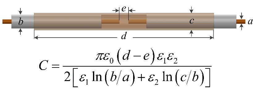
Several modifications were made to the previously proposed self-decoupled coil to introduce flexibility [9]: first, the copper tape (Figure 1a) used as coil conductor was replaced with the central (Figure 1b) or shield conductor (typically copper braid, Figure 1c) of a flexible coaxial cable; second, Xarm (inductor or capacitor) for frequency tuning was integrated with the feed board; third, the lumped Cmode( mode capacitors) opposite the feed port were replaced with coaxial capacitors by wrapping/inserting a short outer shield/central conductor (Figure 1b/Figure 1c).A pair of 7T flexible self-decoupled coils were made from the central conductor of an ultra-flexible low-loss coaxial cable, with the outer jacket and copper braid removed. A plastic sleeve (inner/outer diameter 1.7/2.5 mm, length 2.5 cm) was 3D-printed to bridge two conductors. The outer surface of the sleeve was covered with copper foil, which forms two series coaxial capacitors along with the central conductors inside the sleeve. The sleeve was designed to be solid in the middle (0.5 mm thick) to avoid short circuiting of the two central conductors. Based on the equation in Figure 2, the length of the sleeve was chosen to 2.5 cm, to form an equivalent capacitor of ~0.3 pF [9]. The coil has a diameter of approximately 10 cm when it is circular.
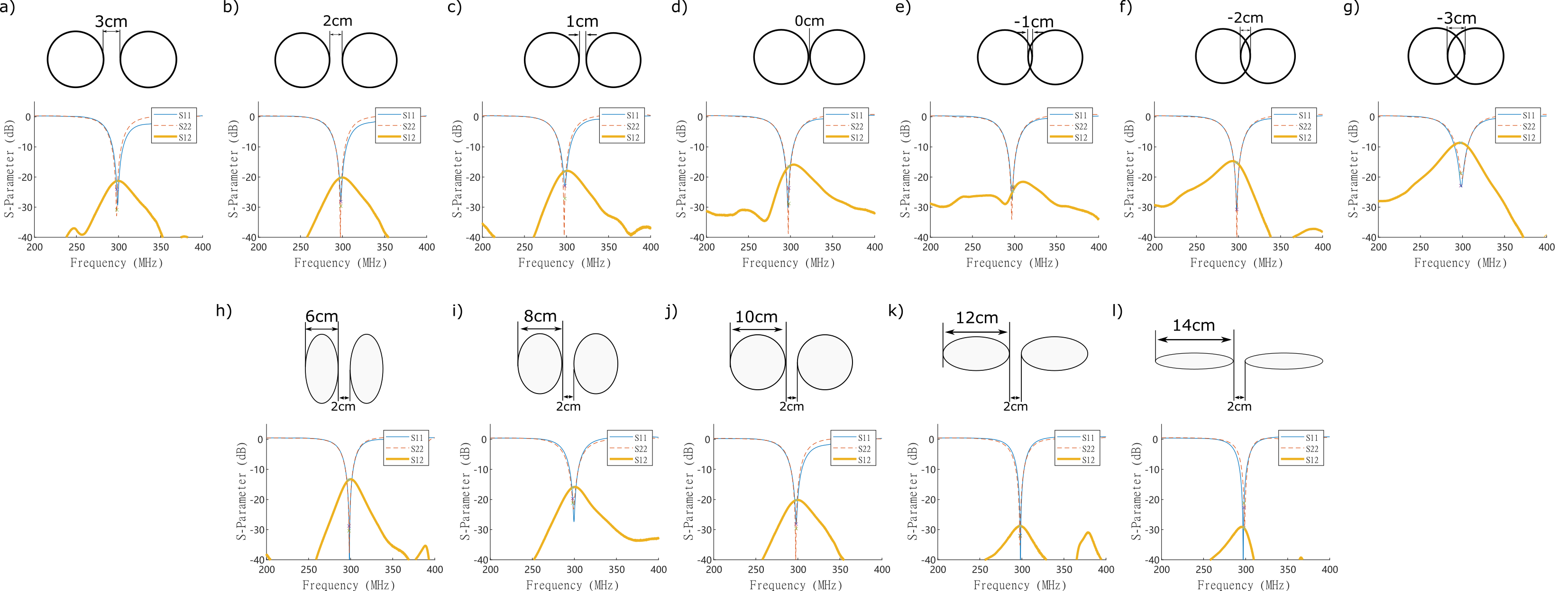
Robustness of coil tuning/matching/decoupling was measured on a cuboid phantom (30 x 30 x 40 cm3, 2.5 cm below the coil) with a Keysight 5071C VNA. Two scenarios were tested (Figure 3): one to investigate the decoupling robustness versus coil separation (coil shape unchanged, circular) and the other to investigate the decoupling versus coil shapes (coil distance unchanged, 2 cm apart).
Results and Discussions:
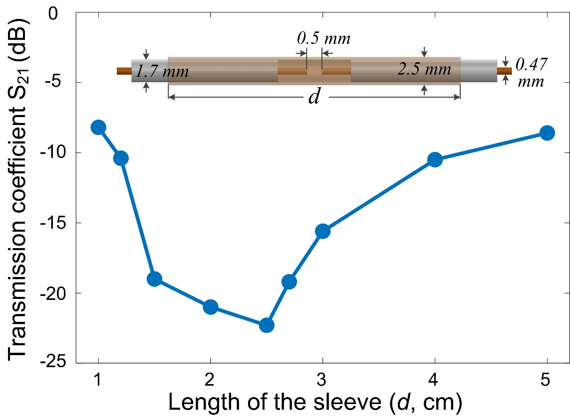
Figure 4a-g shows the S-parameter plots of two flexible, self-decoupled coils with various coil distances. The decoupling could be maintained at a high level of <-15 dB when coils are separated or overlapped (overlapped area <30%). Figure 4h-l plots S-parameter changes when the coils were stretched horizontally or vertically. In both scenarios, i.e., variations of coil distance or variations of shape, the self-decoupled coils remained well-tuned and matched, with S11/S22 better than -20 dB. These features make the coaxial self-decoupled coil well suited for flexible and/or wearable applications.An unexpected benefit of the coaxial self-decoupled coil is that the required sleeve length to form coaxial capacitance is not critical. For the 10-diameter conventional self-decoupled coils, high isolations of <-15 dB can be achieved with sleeve lengths varying from 1.5 cm to 3.5 cm (Figure 5). This eases the fabrication of practical coils.
For simplicity, we used the cable's central conductor for the flexible self-decoupled coil. An alternative way is to use the cable's outer braid, as shown in Figure 1c. When the coil loss dominates, the latter design may be preferred as it has a lower resistance. For most 7T coils (diameter > 2 cm), however, the sample loss dominates and there should be no significant difference by using the central or outer conductor.
Conclusion:
We propose a coaxial self-decoupled transmit/receive coil for ultrahigh field MRI. By integrating the coaxial capacitance with the self-decoupling concept, it exhibits superior decoupling performance when coil distance and/or coil geometry changes, making it suitable for wearable transmit/receive applications to improve imaging performance and patient comfort.Acknowledgements
This work is in part supported by NIH R21 EB029639. Shuyang Chai and Yue Zhu contributed equally to this work.References
[1] K. P. McGee et al., “Characterization and evaluation of a flexible MRI receive coil array for radiation therapy MR treatment planning using highly decoupled RF circuits,” Phys. Med. Biol., vol. 63, no. 8, p. 08NT02, Apr. 2018, doi: 10.1088/1361-6560/aab691.
[2] J. R. Corea et al., “Screen-printed flexible MRI receive coils,” Nat Commun, vol. 7, no. 1, p. 10839, Mar. 2016, doi: 10.1038/ncomms10839.
[3] S. S. Vasanawala et al., “Development and Clinical Implementation of Next Generation Very Light Weight and Extremely Flexible Receiver Arrays for Pediatric MRI,” p. 22.
[4] B. Zhang, D. K. Sodickson, and M. A. Cloos, “A high-impedance detector-array glove for magnetic resonance imaging of the hand,” Nat Biomed Eng, vol. 2, no. 8, pp. 570–577, Aug. 2018, doi: 10.1038/s41551-018-0233-y.
[5] P. B. Roemer, W. A. Edelstein, C. E. Hayes, S. P. Souza, and O. M. Mueller, “The NMR phased array,” Magnetic Resonance in Medicine, vol. 16, no. 2, pp. 192–225, 1990, doi: 10.1002/mrm.1910160203.
[6] X. Zhang and A. Webb, “Design of a capacitively decoupled transmit/receive NMR phased array for high field microscopy at 14.1T,” Journal of Magnetic Resonance, vol. 170, no. 1, pp. 149–155, Sep. 2004, doi: 10.1016/j.jmr.2004.05.004.
[7] B. Wu, X. Zhang, P. Qu, and G. X. Shen, “Capacitively decoupled tunable loop microstrip (TLM) array at 7 T,” Magnetic Resonance Imaging, vol. 25, no. 3, pp. 418–424, Apr. 2007, doi: 10.1016/j.mri.2006.09.031.
[8] B. Wu et al., “7T Human Spine Imaging Arrays With Adjustable Inductive Decoupling,” IEEE Transactions on Biomedical Engineering, vol. 57, no. 2, pp. 397–403, Feb. 2010, doi: 10.1109/TBME.2009.2030170.
[9] X. Yan, J. C. Gore, and W. A. Grissom, “Self-decoupled radiofrequency coils for magnetic resonance imaging,” Nat Commun, vol. 9, no. 1, p. 3481, Aug. 2018, doi: 10.1038/s41467-018-05585-8.
Figures