4495
Prospective Motion Correction and Data Re-acquisition at 7 Tesla using E/M Trackers
W. Scott Hoge1,2, Onur Afacan2,3, Simon K. Warfield2,3, Amir Roth4, and Erez Nevo4
1Radiology, Brigham and Women's Hospital, Boston, MA, United States, 2Dept of Radiology, Harvard Medical School, Boston, MA, United States, 3Computational Radiology Laboratory, Boston Children's Hospital, Boston, MA, United States, 4Robin Medical, Inc., Baltimore, MD, United States
1Radiology, Brigham and Women's Hospital, Boston, MA, United States, 2Dept of Radiology, Harvard Medical School, Boston, MA, United States, 3Computational Radiology Laboratory, Boston Children's Hospital, Boston, MA, United States, 4Robin Medical, Inc., Baltimore, MD, United States
Synopsis
We evaluated the utility of electro-magnetic (E/M) based tracking to correct for motion at 7 Tesla. A 3D Turbo-FLASH sequence was modified to include prospective field-of-view (FOV) steering and track motion events. Custom software provided FOV updates to the TFL sequence from E/M sensor location measurements. Motion events recorded by the software indicated time-periods when acquired data was likely corrupted due to motion. Logic within the sequence re-acquired motion-corrupted k-space data segments to yield high-quality high-spatial-resolution images. Results demonstrate the viability of E/M tracking at 7T.
Introduction
Certain MRI protocols impose relatively long acquisition times, with high-spatial-resolution 3D scans chief among these. Long acquisition times risk a degradation in image quality due to subject motion, and the resulting image may be unusable in the case of severe motion1. Ultra-high field imaging (UHF) at ≥7T field strength holds significant promise, but the achievable spatial resolution may be limited by motion2. Here we present preliminary work on the use of E/M sensors to track a subject’s position over a long scan, prospectively steer the field-of-view to correct for motion, and re-acquire motion corrupted data.Multiple methods to monitor motion during MRI exist, including volume3 and spiral4 navigators, camera systems5, and EM tracking devices6. Navigators are successful in low-duty-cycle pulse sequences with adequate “dead time” into which the navigators can be placed, such as MPRAGE, but are incompatible with sequences that are in high demand for clinical 7T neuroimaging, including angiography, susceptibility-weighted imaging, or vessel wall imaging applications. Camera based systems are unsuitable at 7T because of longer bore lengths and RF signal receiver arrays that cover the face, preventing the camera from having a clear view of the head. We investigate E/M sensors here which are broadly applicable to all pulse sequences and compatible with the 7T Terra (Siemens Healthcare, Erlangen, Germany).
Methods
Figure 1 illustrates the physical layout of our system, following Afacan, et al7. Position measurements were recorded using the EndoScout (Robin Medical, Inc, Baltimore, MD) system. Four small (~1cm) sensors embedded within a headband worn by the subject were employed. When activated by specific gradient pulses from the pulse sequence, the location and vector orientation of each sensor within the bore is recorded.Custom-built Communications Server (CommServ) software records the original position of the sensors at the start of the scan, and compares subsequent measurements to determine field-of-view updates. These updates are transmitted, via ACE8 over TCP/IP, to a client socket within the scanner's image reconstruction pipeline, which posts the updates to shared memory in the sequence. The sequence FOV was updated when a semaphore flag indicated the availability of new steering information.
A time-stamp log of all reported tracker positions was recorded to enable data reacquisition9. Motion events were detected when the sensors moved beyond a specified threshold, here >1mm displacement or >1-degree deflection. Motion-free-periods (MFP) were defined as time between motion events. Every 10 TRs, MFP records were transmitted to the sequence and compared against an internal acquisition history table. Acquisition times falling within the MFP would be marked ’motion free’, and the corresponding lines within the current sequence acquisition loop would be removed. To maintain the real-time run requirements of the scanner, “holes” within the acquisition loop would then be filled with repeated copies of those lines not marked motion free. Scanning stopped when one of two conditions were met: either the maximum number of prescribed volumes have been acquired, or all k-space lines needed to form an image have been marked ’motion free’. The CommServ interface includes a research staff accessible GUI written in Tcl/Tk, and is available in open-source by written request to the authors.
Results
We present results from two experiments. A low-spatial-resolution protocol (1.7mm3 isotropic; TR: 1.95sec; TE: 1.24ms; TI: 900ms; matrix size: 128x128x104; FOV: 22cm x 22cm x 17.68cm) was repeated 4 times under different conditions: {No Motion, With Motion} and {No Correction, With Correction}. Images from each of the 4 possible condition combinations are shown in Figure 2. The top row compares the case of No-Correction versus With-Correction when the subject stayed motionless. These images are nearly identical, demonstrating that the system does not introduce adverse FOV update events in the case of No-Motion. The bottom row compares the case of No-Correction versus With-Correction in the presence of subject motion. The images on the bottom left show typical motion artifacts, which are predominantly removed when the feedback system is enabled, shown on the bottom right. The second experiment, Figure 3, employed a high-spatial resolution protocol (0.86mm x 0.86mm x 1.0mm; TR: 1.91sec; TE: 2.63ms; TI: 900ms matrix size: 256x256x176; FOV: 22cm x 22cm x 17.6cm) with both subject motion and the prospective steering and reacquisition system enabled. The images in Figure 3 illustrate a comparison between the first volume in the presence of motion, and the subsequent images after the prospectively-steered and reacquired data is incorporated into the reconstruction. The line plots in Figure 4 illustrate (top) position, (middle) angular displacement, and (bottom) the ky-line-index acquisition timing over the course of the acquisition. Motion-free periods identified by the CommServ are noted by the gray regions in the plots. We note that although the measured motion is relatively small, significant artifacts are still present in the images generated from the first volume. These artifacts are predominantly corrected in the images that include reacquired and prospectively steered data.Conclusion
We have demonstrated that image artifacts due to subject motion can be mitigated in high-resolution MR protocols at 7T using E/M sensors to track position, prospective steering to update the FOV, and a reacquisition strategy to replace motion-corrupted data.Acknowledgements
This project is supported by NIH grant R44MH086984 and the Department of Radiology at Brigham and Women’s Hospital, Boston, MA.References
- Andre JB, Bresnahan BW, Mossa-Basha M, Hoff MN, Smith CP, Anzai Y, Cohen WA. Toward quantifying the prevalence, severity, and cost associated with patient motion during clinical MR examinations. Journal of the American College of Radiology 2015;12(7):689 –695.
- Bause J, Polimeni JR, Stelzer J, In MH, Ehses P, Kraemer-Fernandez P, Aghaeifar A, Lacosse E, Pohmann R, Scheffler K. Impact of prospective motion correction, distortion correction methods and large vein bias on the spatial accuracy of cortical laminar fMRI at 9.4 Tesla. NeuroImage 2020;208:116434.
- Alhamud A, Tisdall MD, Hess AT, Hasan KM, Meintjes EM, van der Kouwe AJW. Volumetric navigators for real-time motion correction in diffusion tensor imaging. Magnetic Resonance in Medicine 2012;68(4):1097–1108.
- Brown TT, Kuperman JM, Erhart M, White NS, Roddey JC, Shankaranarayanan A, Han ET, Rettmann D, Dale AM. Prospective motion correction of high-resolution magnetic resonance imaging data in children. NeuroImage 2010;53(1):139 – 145.
- Zaitsev M, Dold C, Sakas G, Hennig J, Speck O. Magnetic resonance imaging of freely moving objects: prospective real-time motion correction using an external optical motion tracking system. NeuroImage 2006;31(3):1038 – 1050.
- van der Kouwe A, Fetics B, Polenur D, Roth A, Nevo E. Real-time prospective rigid-body motion correction with the EndoScout gradient-based tracking system. in Proc. 17th ISMRM Meeting. 2009; 4623.
- Afacan O, Wallace TE, Warfield SK. Retrospective correction of head motion using measurements from an electromagnetic tracker. Magnetic Resonance in Medicine 2020;83(2):427–437.
- Schmidt DC. The ADAPTIVE communication environment (ACE™), 1993. Http://www.dre.vanderbilt.edu/ schmidt/ACE.html.
- Benner T, van der Kouwe AJW, Sorensen AG. Diffusion imaging with prospective motion correction and reacquisition. Magnetic Resonance in Medicine 2011;66(1):154–167.
Figures
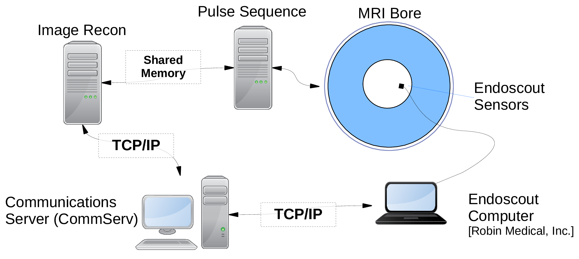
Figure 1: Physical layout of the motion-correction system.
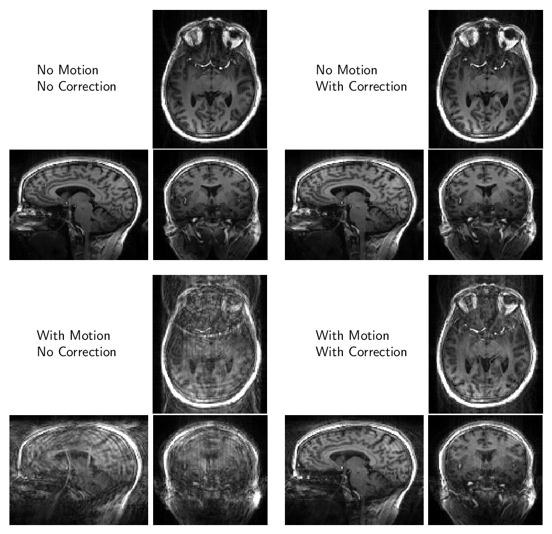
Figure 2: Images demonstrating stability of the motion-correction system. Image quality is maintained in the absence of motion and artifacts are reduced in the presence of motion.
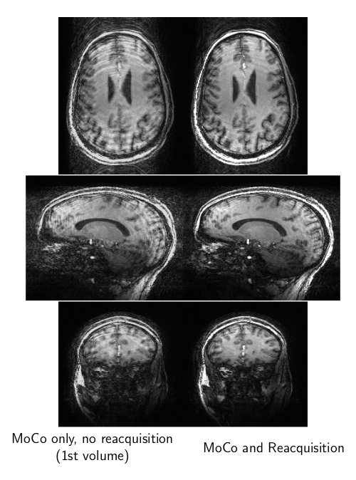
Figure 3: A comparison between motion-corrupted and motion-corrected images. The images to the left show the prospectively-steered first volume of data, during which time the subject moved. The images to the right were reconstructed with motion-corrupted data replaced by prospectively-steered reacquired data.
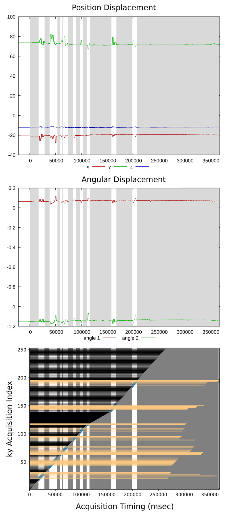
Figure 4: Line plots that show position and angular displacements as well as the acquisition ky-line-index timing over the course of the acquisition for the high-resolution acquisition in Figure 3. Motion-free periods are high-lighted with a gray background.
DOI: https://doi.org/10.58530/2022/4495