4433
Design of a 13-Channel hybrid RF array with field rectification of dielectric material for foot/ankle imaging at 7T1Biomedical Engineering, University at Buffalo, Buffalo, NY, United States
Synopsis
This study proposes a 13-channel hybrid array system consisting of Microstrip transmission line resonators and half-birdcage coil and demonstrates the high-permittivity dielectric material’s positive effect on the B1 field distribution.
Synopsis
This study proposes a 13-channel hybrid array system consisting of Microstrip transmission line resonators and half-birdcage coil and demonstrates the high-permittivity dielectric material’s positive effect on the B1 field distribution.Introduction
Microstrip lines are being used in MR applications due to their unique properties, such as reduced radiation loss, high-frequency capability, and reduced perturbation of sample loading to the RF coil compared to conventional coils. In this study, we propose a 13-channel hybrid array consisting of 12 Microstrips and 1 volume half birdcage coil for the foot/ankle MR imaging at 7T. The high-permittivity dielectric material is applied to rectify the B1 field distribution and coverage.Method
The hybrid array setup consists of a circular array formed by eight microstrip lines, a linear array formed by four microstrip lines, and 1 volume coil placed closely on a foot/ankle phantom. The microstrip lines in the circular array have the following dimensions: length:11.6cm, the width of the strip conductor:1 mm, thickness of the substrate: 1cm. The microstrips were excited via ports with 450 phase differences. The microstrip lines in the linear array have the following dimensions: length:20 cm, the width of the strip conductor:1 mm, thickness of the substrate: 1cm. The legs of the half-birdcage coil are 1 cm wide and 9.2 cm long. There are seven legs in the volume coil, which are fed via ports with 450 phase differences. All the channels were matched to 300MHz using appropriate capacitor values. The capacitor values for 11.6 cm long Microstrip lines were 6.15pF, 2.7pF for 20 cm long Microstrip lines, and 8.85pF for the volume coil. We added a 4mm thick high-dielectric sheet below the foot/ankle phantom and varied the relative permittivity values to evaluate the performance. We performed Electromagnetic simulations where all the channels were excited and evaluated the B fields and SAR produced by them. B field distribution along the axial and sagittal plane of the phantom was reconstructed and analyzed.Material Specifications
Microstrip substrate: RO4003C Laminate
• Relative permittivity: 3.38
• Relative permeability: 1
• Electrical conductivity: 0 s/m
Human Foot/Ankle phantom:
• Relative permittivity:39
• Relative permeability: 1
• Electrical conductivity: 0.49 s/m
Strip conductor & volume coil: Copper
Results
The simulation results of the 13-Channel hybrid array system for foot/ankle imaging at 7T,300 MHz are obtained as shown in the following figuresDiscussion/Conclusion
The 13-Channel hybrid array system consisting of microstrips and volume was successfully designed and evaluated for foot/ankle imaging at 7T. We were able to generate B fields covering every part of the foot/ankle phantom. The half-birdcage coil used in the hybrid array may pose limitations to the parallel imaging capability, despite providing an extensive and uniform B1 field coverage. Thus, further modifications may help improve the performance of this multichannel coil array system. The high-permittivity dielectric sheet showed a positive impact on the uniformity of the magnetic field distribution. The imaging safety has been investigated through SAR calculation with the foot/ankle phantom.Acknowledgements
No acknowledgement found.References
- Zhang X, Ugurbil K, Chen W. Microstrip RF surface coil design for extremely high-field MRI and spectroscopy. Magn Reson Med. 2001 Sep;46(3):443-50. doi: 10.1002/mrm.1212. PMID: 11550234
- Santini T, Kim J, Wood S, et al. A new RF transmit coil for foot and ankle imaging at 7T MRI. Magn Reson Imaging. 2018;45:1-6. doi:10.1016/j.mri.2017.09.005
- Pang Y, Wu B, Jiang X, Vigneron DB, Zhang X. Tilted microstrip phased arrays with improved electromagnetic decoupling for ultrahigh-field magnetic resonance imaging. Medicine (Baltimore). 2014;93(28):e311. doi:10.1097/MD.0000000000000311
- Zhang X, Ugurbil K, Sainati R, Chen W. An inverted-microstrip resonator for human head proton MR imaging at 7 tesla. IEEE Trans Biomed Eng. 2005 Mar;52(3):495-504. doi: 10.1109/TBME.2004.842968. PMID: 15759580.
Figures
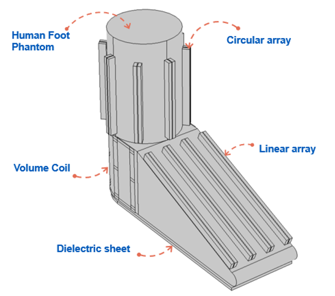
Figure 1: Image shows the hybrid array setup closely placed on the human foot/ankle phantom.
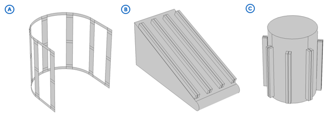
Figure 2: (A) volume coil (half birdcage) coil placed on the phantom to cover the heel region of the human foot. (B) Linear array formed by four microstrip lines to cover the metatarsals and phalanges region of the human foot. (C) The circular array is formed by eight microstrip lines to cover the ankle region.
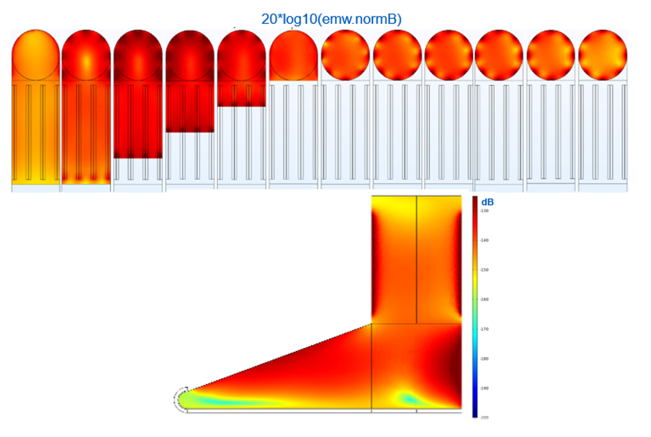
Figure 3: Image shows Magnetic field distribution without any dielectric sheet placed below the foot phantom.
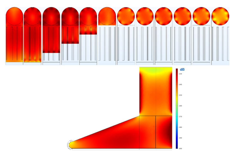
Figure 4: Image shows Magnetic field distribution with a dielectric sheet placed below the foot phantom having relative permittivity, εr = 500. Much improved B1 coverage in the sole area is observed.
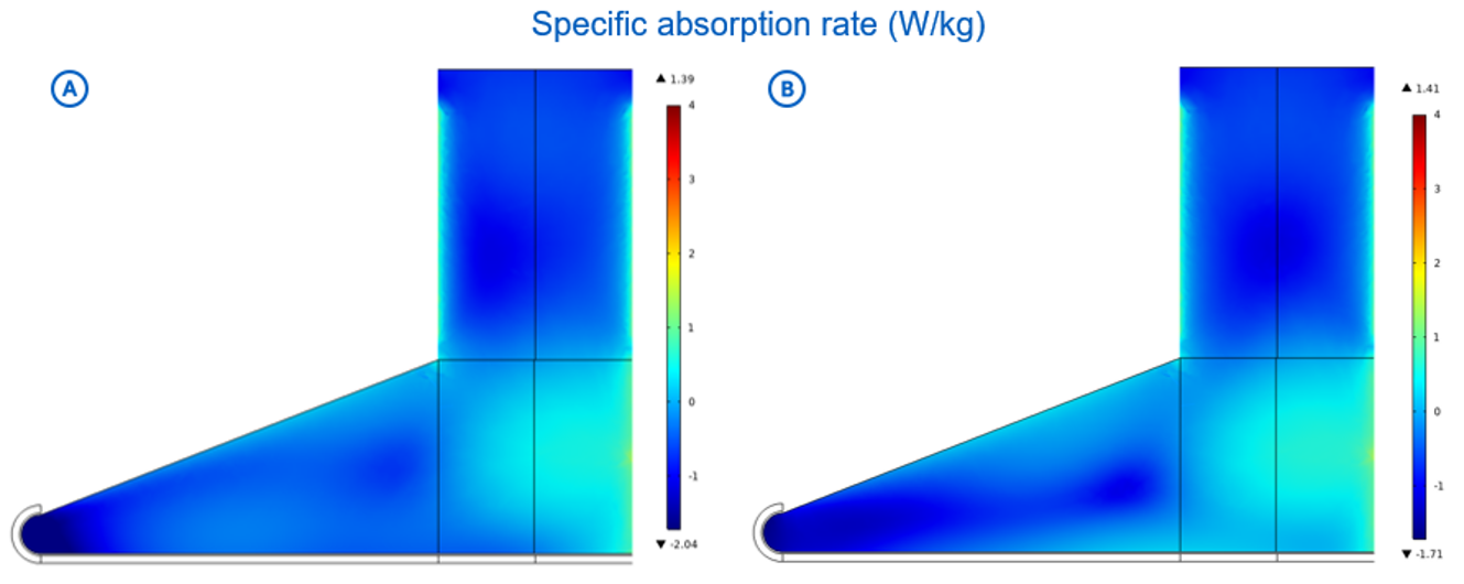
Figure 5: (A) figure shows the SAR in the setup without the dielectric sheet. (B) the figure shows the SAR in setup with the dielectric sheet, εr = 500