4395
Utilization of high resolution and low velocity encoding PCA with highly accelerated compressed sensing for preoperative SEEG planning1Department of Neurosurgery, Clinical Neuroscience Center, Ruijin Hospital, Shanghai Jiao Tong University School of Medicine, Shanghai, China, 2Clinical Neuroscience Center, Ruijin Hospital Luwan Branch, Shanghai Jiao Tong University School of Medicine, Shanghai, China, 3United Imaging Healthcare, Shanghai, China, 4Department of Radiology, Ruijin Hospital Luwan Branch, Shanghai Jiao Tong University School of Medicine, Shanghai, China, 5Central Research Institute, United Imaging Healthcare, Shanghai, China
Synopsis
It is essential to avoid small vessels during stereo-electroencephalography (SEEG) electrode implantation. In this study, we proposed a 6-fold Compressed sensing accelerated, 5cm/s Low velocity encoded, 0.75mm Isotropic resolution Phase contrast Magnetic Resonance Angiography (CLIP-MRA). In CLIP-MRA, the compressed sensing based acceleration method was shown to achieve better image quality or shorter scan duration compared to parallel imaging based acceleration. CLIP-MRA was able to display not only cortical arteries and veins simultaneously, but also vessels in the skull. Safety and effectiveness of CLIP-MRA utilized preoperative SEEG planning were evaluated on a small patient cohort.
Introduction
At present, computerized tomographic angiography (CTA), digital subtraction angiography (DSA) and contrast enhanced magnetic resonance angiography (CEMRA) 1 are commonly used in the avascular trajectory planning to identify vessels to avoid intracranial hemorrhage 2 during SEEG electrode implantation. Non-contrast enhanced MRA has been evaluated 3, as Phase Contrast magnetic resonance Angiography (PCA) was able to display blood vessels based on the phase change generated by flowing spins. However, the acquisition time is extremely long for high resolution and low velocity encoding (VENC) setting when small vascular were to be displayed. Therefore, in spite of the risks of additional radiation and iodine allergy, traditional non-contrast enhanced MRI could hardly replace CTA or DSA due to its long scan time.In this study, we implemented a 6-fold Compressed sensing 4 accelerated, 5cm/s Low velocity encoded, 0.75mm Isotropic Phase contrast Magnetic Resonance Angiography (CLIP-MRA) to achieve whole brain vascular display in 7min 32sec. The effectiveness of CLIP-MRA has been evaluated on 11 patients who underwent electrode placement under robotic assistance planning. The amount of visualized vessels was evaluated on each patient, and intracranial hemorrhage, infection and other serious complications during the operation were observed.
Methods
Compressed sensing reconstruction:We applied a formerly reported reconstruction procedure 5 which combines compressed sensing, parallel imaging and half Fourier acquisition in CLIP-MRA.
MR Scan:
A cohort of 11 consecutively enrolled patients (three males and eight females, mean: 34.4 years old, range: 7–52 years) who would accept SEEG implantation afterwards, underwent MR scans at Ruijin Hospital between July and October 2021 on a 3.0 T scanner (uMR 890, United Imaging Healthcare, Shanghai, China) with a dedicated 64-channel head coil. CLIP-MRA (Sagittal plane, FOV: 205×215×230mm3, voxel: 0.75×0.75×0.75 mm3, acceleration factor: 6, VENC: 5cm/s in readout, phase encoding, and slice direction, scan duration: 7min 32sec), T1 MPRAGE and 3D T2-FLAIR were acquired for all patients.
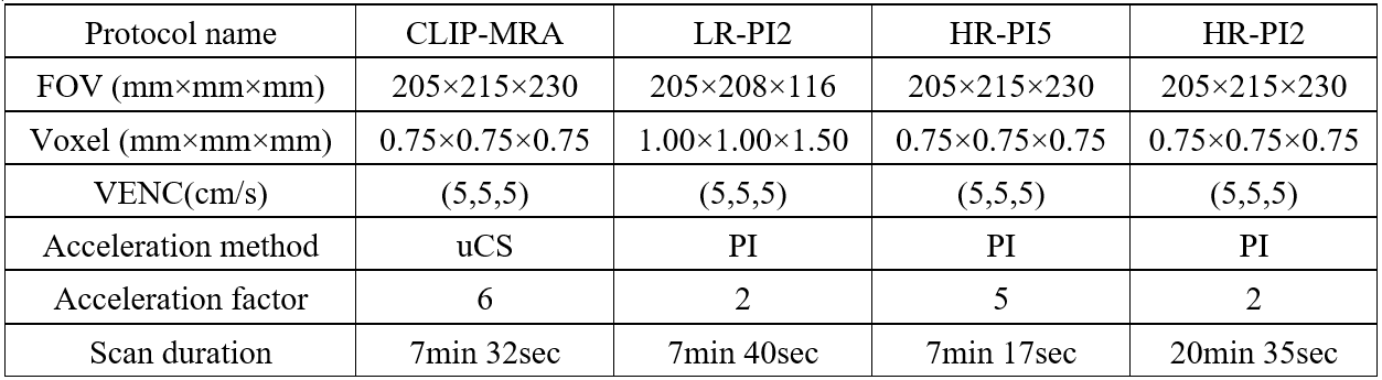
In addition, to evaluate the performance of CLIP-MRA, CLIP-MRA and other three PCA protocols with parallel imaging (PI) were applied for comparison in one pathology case. The other three protocols were named as LR-PI2 (Low resolution with 2-fold PI), HR-PI5 (High resolution with 5-fold PI) and HR-PI2 (High resolution with 2-fold PI). The parameters of four protocols are summarized in Table 1.
Surgical planning:
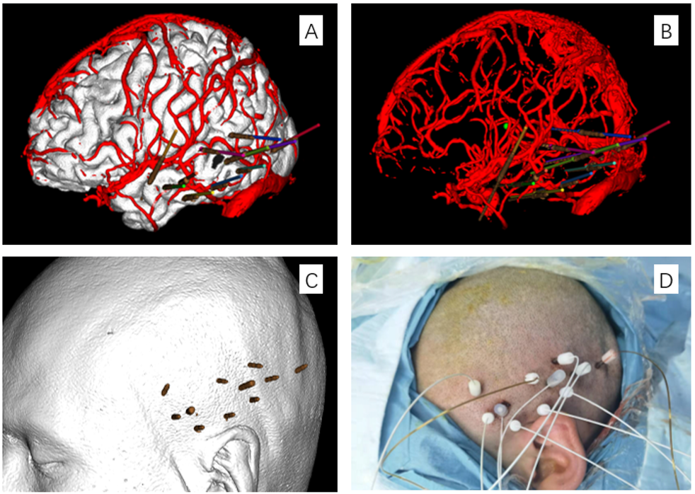
All patients underwent CLIP-MRA and CTA scan before SEEG implantation. T1 and T2 FLAIR data were transferred to a Sinovation planning station (version 2.0.1.2; a portable computer; Sinovation, Beijing, China) for surgical planning, and CLIP-MRA data were used for avascular trajectory planning. We adjusted the entering point and targeting point of the electrode trajectory on CLIP-MRA images and CLIP-MRA-3D vessel model to ensure the straight-line distance between the trajectory and the blood vessel was more than 2mm (safety range: 2mm radius). Bone fiducials were utilized for robotic registration and all patients underwent head CT scans after bone fiducials placement. Implantation procedures were performed using the Sinovation robot system and all patients underwent intraoperative CT scanning to verify the position of each electrode and to identify any signs of intracranial hemorrhage immediately after implantation.
Results
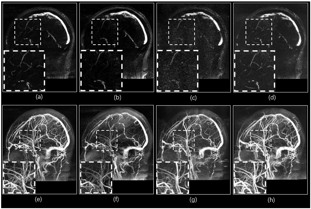
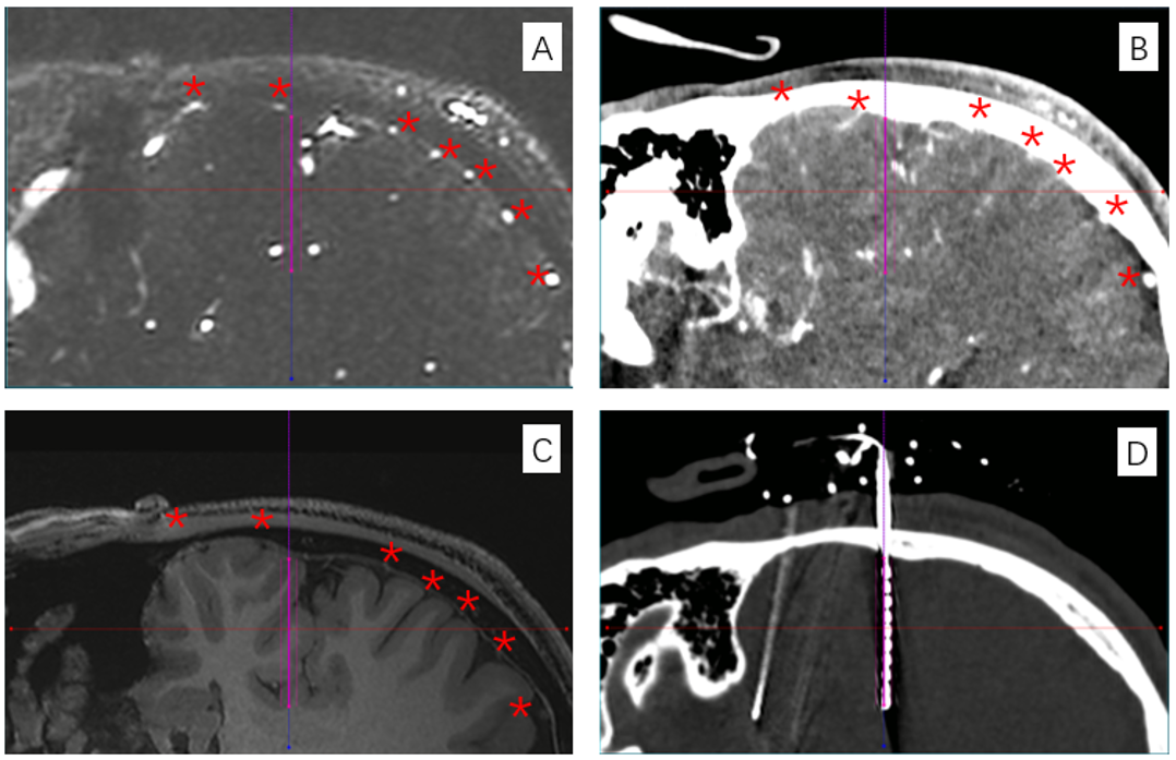
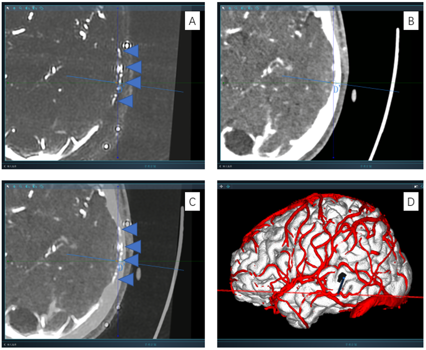
The comparison of the four series of image results from CLIP-MRA, LR-PI2, HR-PI5 and HR-PI2 is illustrated in Figure 1. With similar scan durations, CLIP-MRA achieved higher image quality and higher spatial resolution (voxel size: 0.75 vs. 1.0 mm3) compared with LR-PI2, and provided significant higher imaging quality compared with HR-PI5. With the same spatial resolution, the image quality of CLIP-MRA is nearly equivalent to HR-PI2 but significant shorter scan duration (7:32 vs. 20:35).As shown in figure 2, the presents of cortex vessels in CLIP-MRA are obviously clearer than in CTA because CLIP-MRA is not effected by the skull signal. CLIP-MRA clearly displays cortical arteries and veins simultaneously, which could be hardly achieved by CTA (figure 3). Besides, we found that CLIP-MRA shows middle meningeal arteries as well, which would not be shown on CTA images (figure 4). Such advantages of CLIP-MRA are conducive to the planning of avascular trajectory.
In our cohort, a total of 121 electrodes were implanted, as each of 11 patients received an average of 12 electrodes (range, 10–15). None of the patients had intracranial hemorrhage or infection and no other serious complications were observed.
Conclusions
CLIP-MRA was used for avascular trajectory planning during SEEG procedures, and provided simultaneous visualization of cortical arteries, veins and middle meningeal arteries without radiation exposure, intra-arterial catheter placement or iodinated contrast medium within an acceptable scan duration. The safety and effectiveness of this method has been verified in the small cohort. Further studies involving a larger cohort are needed to verify the safety and reliability of this method.Acknowledgements
We sincerely thank the participants in this study.References
1. Krasimir Minkin, et al. Stereoelectroencephalography Using Magnetic Resonance Angiography for Avascular Trajectory Planning: Technical Report. Neurosurgery. 2017; 81(4):688–695
2. Zuluaga MA, et al. Stability, structure and scale: improvements in multi-modal vessel extraction for SEEG trajectory planning. International Journal of Computer Assisted Radiology and Surgery. 2015; 10(8):1227-1237.
3. Liu, Wenbo, et al. “Cortical vessel imaging and visualization for image guided depth electrode insertion.” Computerized medical imaging and graphics: the official journal of the Computerized Medical Imaging Society vol. 37,2 (2013): 123-30.
4. Lustig, Michael, et al. "Compressed sensing MRI." IEEE signal processing magazine 25.2 (2008): 72-82.
5. Li, Guobin, et al, An L1-norm phase constraint for half-Fourier compressed sensing in 3D MR imaging, Magnetic Resonance Materials in Physics Biology and Medicine. 2015; 28(5) 459–472.
Figures