4114
Comparison of 64-channel and 32-channel head arrays at 7T and 10.5T in full-wave simulation1Advanced Imaging Research Center, UTSouthwestern Medical Center, Dallas, TX, United States, 2Center for Magnetic Resonance Research (CMRR), University of Minnesota, Minneapolis, MN, United States, 3Center for Advanced Imaging Innovation and Research (CAI2R), Department of Radiology, New York University Grossman School of Medicine, New York, NY, United States
Synopsis
Idealized analytical electromagnetic (EM) models predict a spatially non-uniform signal-to-noise-ratio (SNR) gain with increasing coil elements and magnetic field strength. Using realistic EM models, we calculated the performance of prototype 32- and 64-channel receive head arrays at 7T and 10.5T using full-wave simulation with a head-mimicking gel phantom. We obtained SNR and g-factor results in agreement with predictions from ultimate intrinsic calculations, showing ~2-fold SNR gains for a large central region for 64 channels at 10.5T vs. 7T, and lower g-factors with the higher field and higher channel counts; peripheral SNR depended on both field magnitude and channel count.
INTRODUCTION
Analytical electromagnetic (EM) models had previously revealed that higher signal-to-noise ratio (SNR) is attained with more coil elements in a radiofrequency (RF) coil array at ultra-high magnetic fields (1). Analytical simulations, however, are usually performed for an ideal situation. Our recent work showed that realistic EM models reflecting or approaching true experimental conditions are needed to accurately predict the performance of a given coil array at ultra-high field (2). Therefore, realistic EM models of dense array prototypes are needed to validate and/or refine the findings from analytical EM models, even though such simulations are time consuming due to the fine meshing required for dense arrays. In this work, we simulated 32- and 64-channels array prototypes based on a previously presented experimental array layout (3), both at 7 Tesla (T) and 10.5T. We compared the performance in terms of SNR and g-factor (4).METHOD
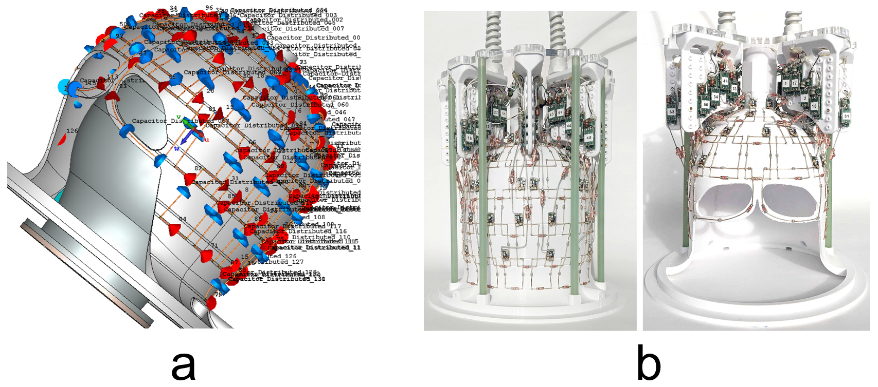
We used the 3D computer aided design software SolidWorks (Dassault Systemes SolidWorks Corp., Concord, Massachusetts) to model the experimental setup, including the coil frame, the array layout, the RF shield in the system, the gel phantom, and the location of the gel phantom. We then imported the 3D model file to CST Microwave Studio (Computer Simulation Technology, CST, Darmstadt, Germany) for EM modeling. The dielectric properties of the gel phantom were set as εr=47.25, σ=0.646 S/m at 447MHz (1H frequency at 10.5T) and εr=49.56, σ=0.561 S/m at 297.2MHz (1H frequency at 7T). Fixed capacitors with the same capacitance as employed in the actual prototype were placed on each coil element, and 0.5 Ohm was added in each fixed capacitor. Two 50-Ohm ports were placed on each coil element, one at the location of the variable tuning capacitor, and the other at the port. Co-simulator in CST was used to tune and match each coil. To mimic the preamp decoupling effect, one large impedance (2500 Ohm) was placed at the ports of all other coil elements when tuning and matching an individual coil, and when reconstructing the EM fields. The EM model and pictures of the 64-channel array prototype are shown in Figure 1. The modeled coils were numbered in the same order that was used to group the coil elements in the 64-channel array prototype. Electric and magnetic fields were exported from CST. The electric fields were employed to calculate the intrinsic noise correlation matrix, the magnetic fields to calculate the receive coil sensitivities. The SNR was then estimated at every voxel for an optimal combination of the coils’ contributions (5,6).RESULT AND DISCUSSION
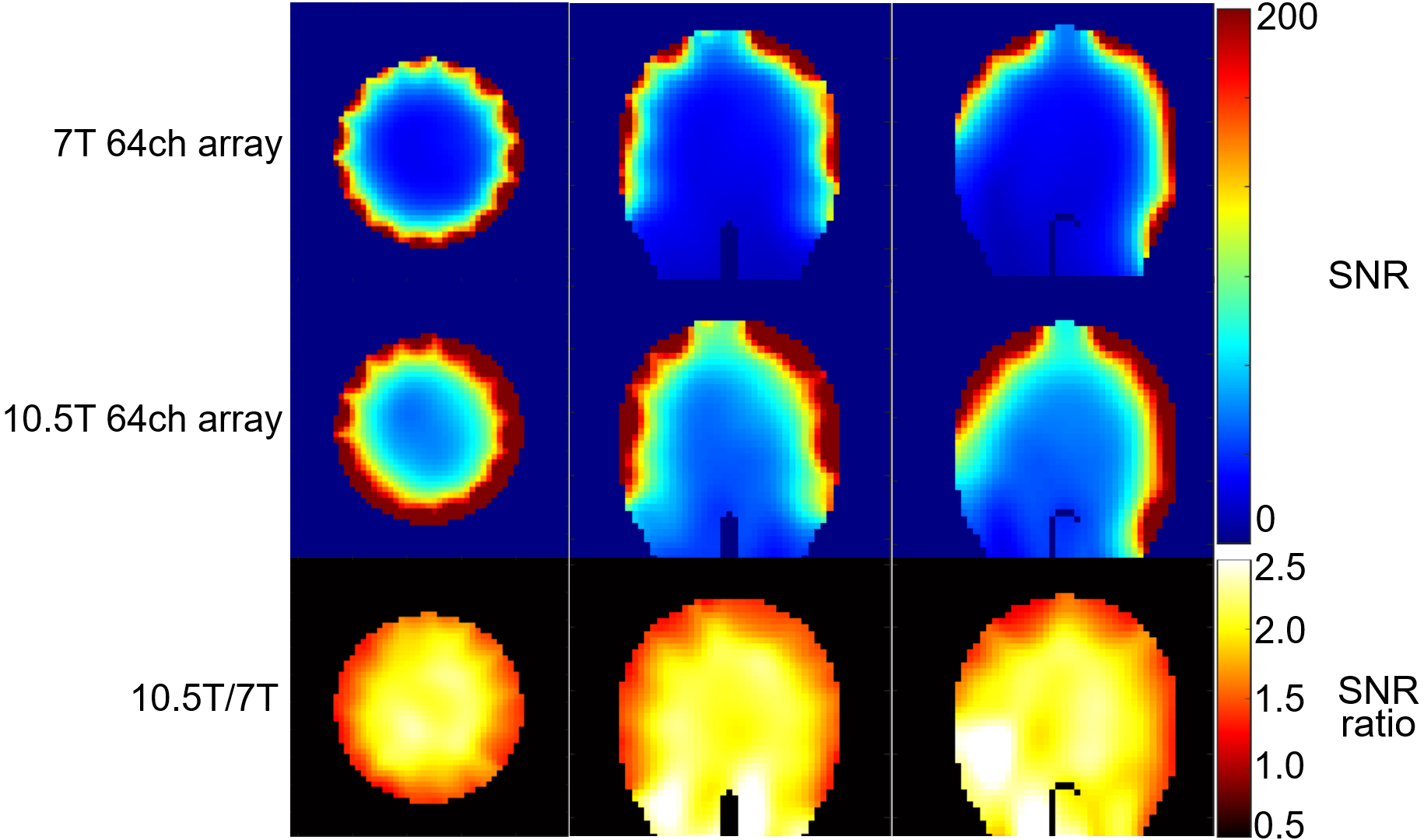
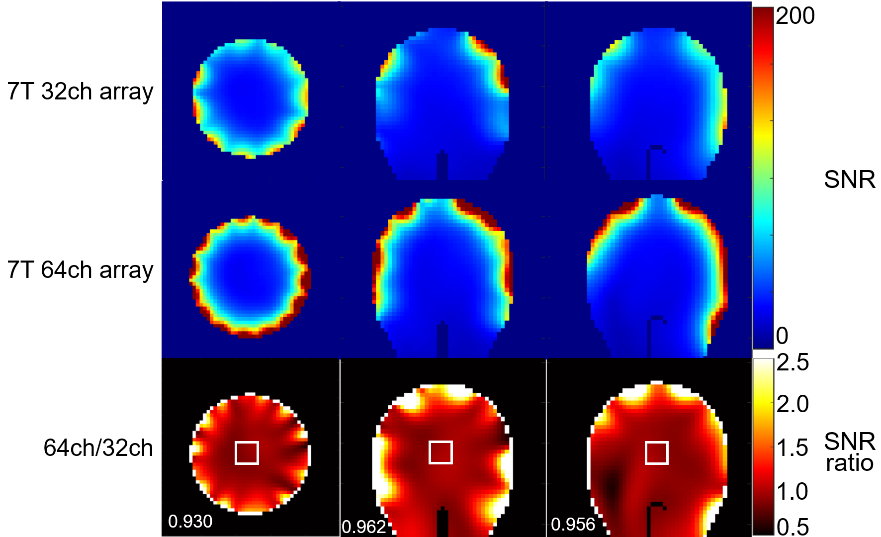
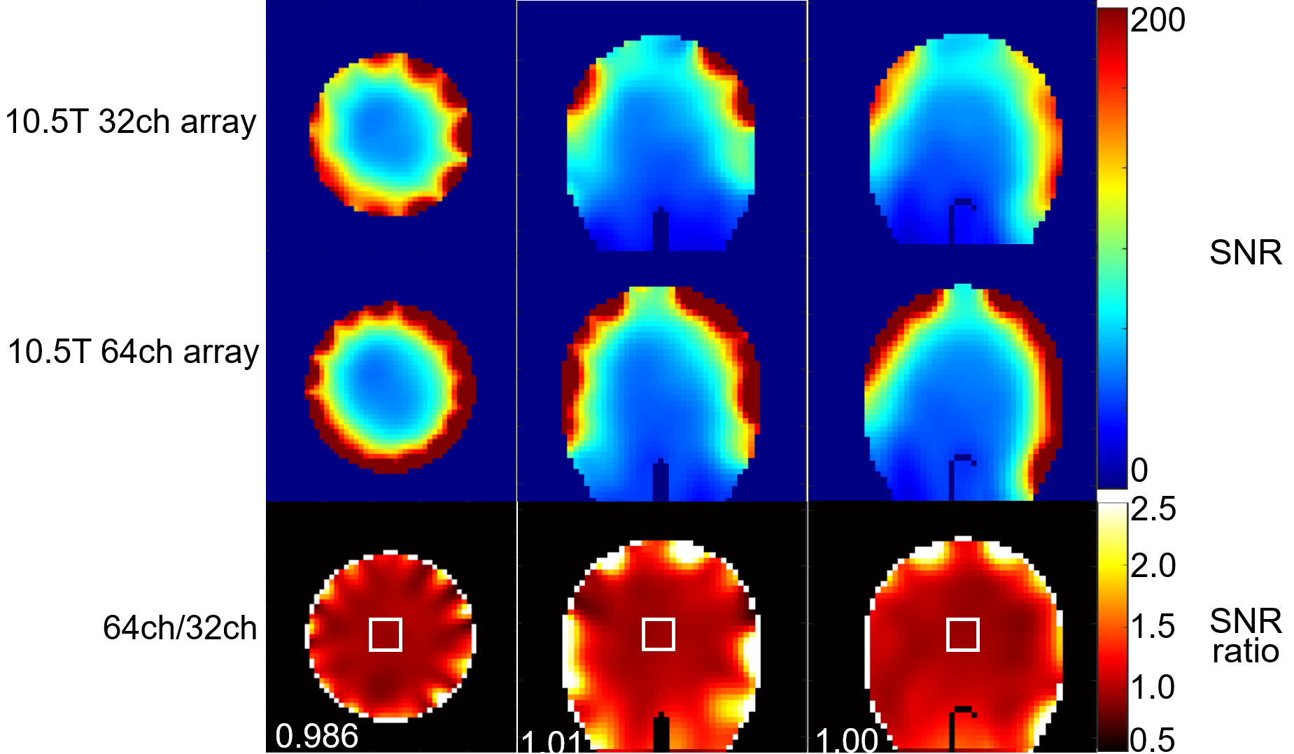
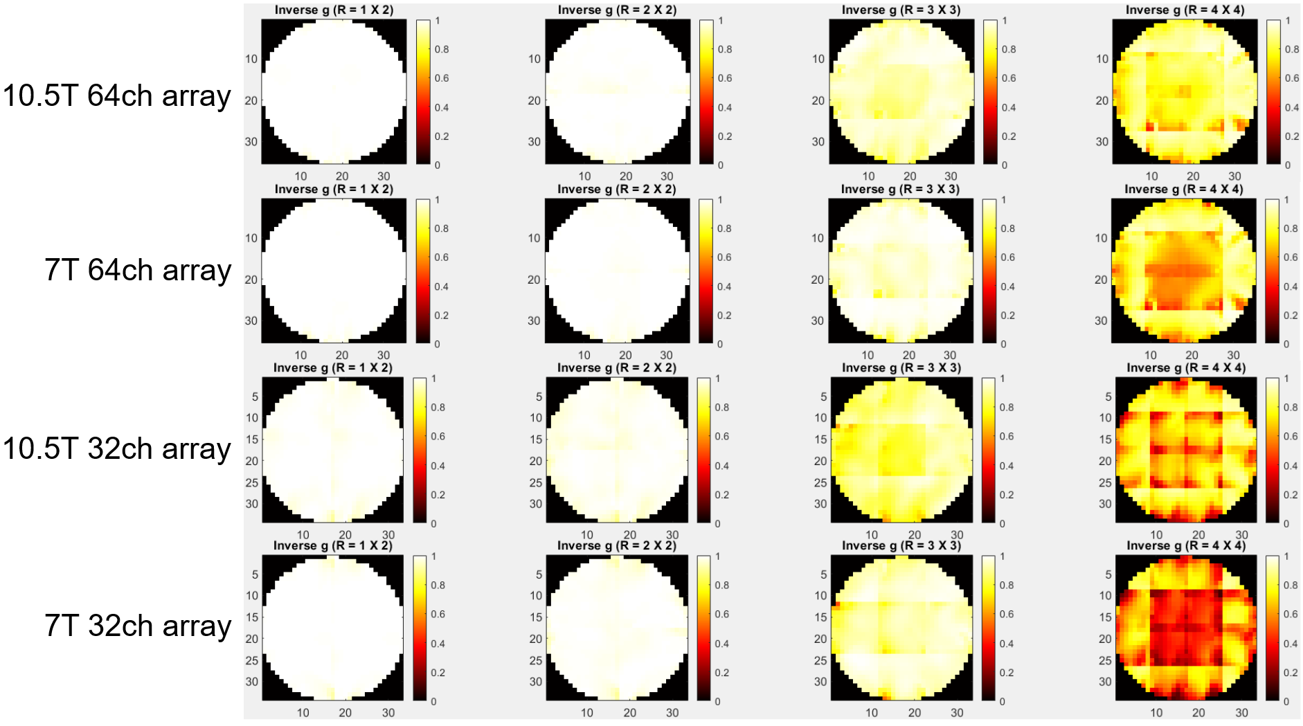
Figure 2 shows SNR maps of the 7T and 10.5T 64-channel arrays. Going from 10.5T to 7T, the SNR of the 64-channel array increased 2.2 times in the central region and ~1.5 times in the periphery, which is in close agreement with the corresponding field dependence of the ultimate intrinsic SNR (uiSNR) (7). The 10.5T versus 7T SNR ratio was in ~2 fold in most of the brain. Figures 3 and 4 compares the SNR maps of the 64- and 32-channel arrays at 7T and 10.5T, respectively. At 7T, the 64-channel array had a more symmetrical SNR profile than the 32-channel array, as well as higher SNR in a narrow peripheral region and slightly lower central SNR, due to the 0.5 Ohm added to each fixed capacitor for soldering and conductive losses. The SNR drop in the center could further increase after adding noise losses from other electronic components, such as preamplifiers. At 10.5T, the 64-channel array also had a more symmetrical SNR profile than the 32-channel array, as well as higher peripheral SNR. Unlike the 7T case, the central SNR was comparable. Figure 5 shows inverse g-factor maps of all arrays for different acceleration factors. The 10.5T 64-channel array yielded the best acceleration performance. For the same number of coil elements, the acceleration performance was higher at 10.5T than 7T, as expected, because the shorter wavelength at higher field strength improves the encoding capability of the coils. For the same frequency, 64 coils yielded higher acceleration performance than 32 coils, as expected. We already completed the construction of the 10.5T 64-channel array and we are in the process of duplicating it for 7T, in order to compliment simulation comparison presented here with experimental data.CONCLUSION
In this work, we use full-wave simulation to compare the performance of 32- and a 64-channel receive head arrays at 7T and 10.5T. Our results, based on realistic EM modeling, revealed ~2-fold gain (~B02 dependence) over a large central region and ~1.5 fold gain peripherally (B0 dependence) for the 64-channel array at 10.5T vs. 7T, in agreement with uiSNR calculations. Due to noise losses from the electronics, the central SNR was slightly lower for the 64-channel array compared to the 32-channel array at 7T, but not in the 10.5T case. The best performance in overall SNR and acceleration was provided by the 10.5T 64-channel array. In conclusion, while SNR gains are possible in a narrow strip in the periphery at 7T with higher channel counts, obtaining SNR gains throughout the head requires both higher magnetic field strength and the denser arrays.Acknowledgements
This research was funded by U01 EB025144, CPRIT RR180056, NIH BTRC P41 EB027061, NIH S10 RR029672, NIH R01 EB024536, NIH P41 EB017183 grants.References
1. Vaidya MV, Sodickson DK, Lattanzi R. Approaching Ultimate Intrinsic SNR in a Uniform Spherical Sample with Finite Arrays of Loop Coils. Concepts Magn Reson Part B Magn Reson Eng 2014;44(3):53-65.
2. Zhang B, Radder J, Adriany G, Ugurbil K, Lattanzi R. The importance of accurate electromagnetic modeling of radiofrequency coil arrays at ultrahigh field MRI. Proc Int Soc Magn Reson Med 30 (2022) 2022:Submitted.
3. Tavaf N, Lagore R, Jungst S, Radder J, Grant A, Auerbach E, Moeller S, Ugurbil K, Adriany G, Van de Moortele P. A Self-decoupled 64 Channel Receive Array for Human Brain MRI at 10.5T. 2021. p 179
4. Tavaf N, Lagore RL, Jungst S, Gunamony S, Radder J, Grant A, Moeller S, Auerbach E, Ugurbil K, Adriany G, Van de Moortele PF. A self-decoupled 32-channel receive array for human-brain MRI at 10.5 T. Magn Reson Med 2021;86(3):1759-1772.
5. Roemer PB, Edelstein WA, Hayes CE, Souza SP, Mueller OM. The NMR phased array. Magn Reson Med 1990;16(2):192-225.
6. Lattanzi R, Grant AK, Polimeni JR, Ohliger MA, Wiggins GC, Wald LL, Sodickson DK. Performance evaluation of a 32-element head array with respect to the ultimate intrinsic SNR. NMR Biomed 2010;23(2):142-151.
7. Guerin B, Villena JF, Polimeridis AG, Adalsteinsson E, Daniel L, White JK, Wald LL. The ultimate signal-to-noise ratio in realistic body models. Magn Reson Med 2017;78(5):1969-1980.
Figures