4113
A 15-channel End-coated Half-wave Dipole Antenna Array System for Foot/Ankle/Calf Imaging at 7T1Biomedical Engineering, University at Buffalo, Buffalo, NY, United States
Synopsis
This study proposes a new 15-channel end-coated half-wave dipole antenna array system for foot/ankle/calf imaging at 7T. The ends of the dipole antennas, operating at 300MHz, are coated with a high-permittivity dielectric material to decrease their length and flatten the B1 field simultaneously. The end-coated dipole antennas are placed around the region of interest to gain the required B1 coverage in the imaging target.
Introduction
Half-wave dipole antennas offer numerous advantages and are considered ideal for Ultra-high field Magnetic Resonance Imaging. However, their half-wave resonant property leads to a significant variation of B1 intensity, which makes the B1 field of the coil array inhomogeneous. Additionally, it isn't easy to design the dipole with the desired length at a given frequency. In this study, we designed a new half-wave dipole antenna array system consisting of 15 half-wave dipole antennas. The ends of each of the dipole conductors were coated with a high-permittivity dielectric material. The array system designed is specifically for the lower extremity imaging and can be used to image the human foot, ankle, and calf region. Due to the irregular and complex shape of the human leg, it is technically challenging to build an array with a sufficient and uniform B1 coverage for imaging this region. We demonstrate that our proposed array system can efficiently cover each human foot, calf, and ankle region and produce uniform and robust B1 fields in the region of interest at the ultrahigh field of 7 Tesla.Method
The proposed array system consists of 15 End-coated dipole antenna elements with their lengths ranging from 20 cm to 40 cm. Fig.1c shows same-sized elements placed in groups. According to their groups, the dimensions and the parameters used to tune all the elements are stated in Table.1. We used a Human leg phantom closely resembling the human foot in dimensions and shape for simulation purposes. The human leg phantom can be seen in Fig.1 a, b. The material properties used for the knee phantom are as follows: εr: 40, conductivity: 0.08 s/m, relative permeability: 1. We matched every element at 300MHz by using appropriate parameters such as high-permittivity dielectric material, thickness, and length of the dielectric material. Each element was excited using an individual lumped port and appropriate phase. The input power was specified as 1 W for each element. We evaluated B1 field distribution, Electric field distribution, and Specific Absorption Rate (SAR) produced by the proposed array in the human leg phantom using Electromagnetic simulations in COMSOL Multiphysics.Results
Fig. 2 a. shows the SAR evaluation produced by the proposed 15-channel array. The proposed array produced a maximum SAR value of 0.75 W/kg in the region of interest, which is essentially a human leg phantom. Further, Fig. 2 b. shows Electric field distribution in the sagittal plane of the human leg phantom, and Fig. 2 c. shows Electric field distribution in the axial planes of the human leg phantom. Finally, Fig.2 d. shows B1 field distribution in the sagittal plane of the phantom, and Fig.2 e. shows B1 field distribution in the axial planes of the human leg phantom. The electric field distribution is demonstrated using a linear scale in V/m, while the B1 field distribution is shown in dB using a logarithmic scale.Discussion/Conclusion
In this study, we successfully designed a 15-channel End-coated half-wave dipole antenna array system. We used dipole antennas of different lengths while resonating at the same frequency of 300MHz, with the shortest being a 20cm dipole antenna without bending the conductors and using meander elements. The dielectric material effectively helped tune all the dipole antennas at 300MHz. The array system successfully produced B1 fields covering every region of the human leg phantom. The B1 field distribution was uniform throughout the human leg phantom. Further, the local SAR values produced by the proposed array system were under the FDA limits.Acknowledgements
No acknowledgement found.References
1. Aditya Bhosale, Leslie L Ying, Xiaoliang Zhang. Design of a 19-Channel hybrid array system for Foot/Ankle Imaging at 7T. ISMRM 2021
2. A.J. Raaijmakers, O. Ipek, D.W. Klomp, C. Possanzini, P.R. Harvey, J.J. Lagendijk, C.A. van den Berg, Magn. Reson. Med. 66, 1488–1497 (2011)
Figures
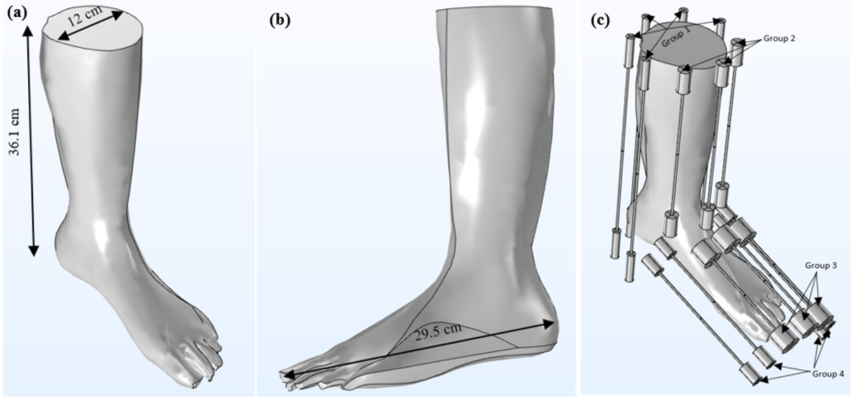
Figure 1. Human Leg phantom and the 15-channel end-coated half-wave dipole antenna array system. (a)3D view of the human leg phantom and the dimensions (b)Side view of the human leg phantom and the dimensions (c)15-channel end-coated half-wave dipole antenna array system loaded with the human leg phantom. The figure also highlights the same-sized dipole antennas in the groups.
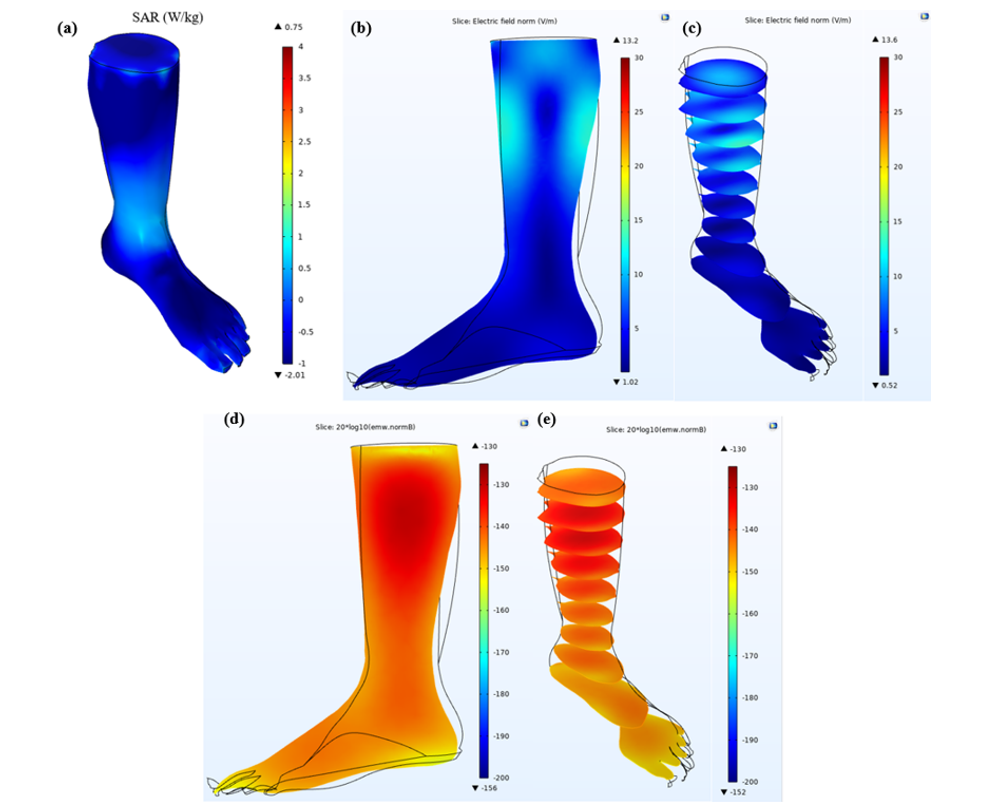
Figure 2. Field distributions produced by the proposed array system. (a)local SAR distribution. Maximum value: 0.75 W/kg (b)Electric field distribution in the sagittal plane. (c) Electric field distribution in axial planes. (c) B1 field distribution in the sagittal plane. (Logarithmic scale: 20*log10(emw.normB)) (d)B1 field distribution in axial planes.
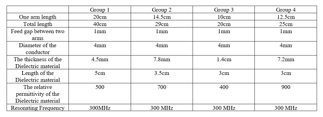
Table 1. The table shows the dimensions and the other parameters used to tune each dipole antenna at 300MHz.