4111
7 Tesla 16-channel transceiver loop array for simultaneous head and cervical spinal cord imaging1Advanced Imaging Research Center, UTSouthwestern Medical Center, Dallas, TX, United States, 2Graduate school, University of Texas Dallas, Richardson, TX, United States, 3Max Planck Institute for Biological Cybernetics, Tuebingen, Germany
Synopsis
Simultaneous assessment of the brain and the cervical spinal cord is of great importance in clinical decision making in areas such as head & neck cancer, traumatic injury, multiple sclerosis or stroke. The small diameter of the cervical spinal cord necessitates high spatial resolution, so there is a growing need to provide 7T simultaneous head and cervical spinal cord imaging, to greatly benefit from increased signal-to-noise ratio and contrast at ultrahigh field. In this work, we developed a 7T 16ch transceiver array that is capable for simultaneous and high-resolution brain and cervical spinal cord imaging.
Introduction
Simultaneous assessment of the brain and the cervical spinal cord is of great importance in clinical decision making in areas such as head & neck cancer, traumatic injury, multiple sclerosis or stroke. However, the small diameter of the cervical spinal cord necessitates high spatial resolution to minimize partial volume effects between the gray matter (GM) and the white matter (WM); so this necessitates a growing need to provide 7T simultaneous head and cervical spinal cord imaging, to greatly benefit from increased signal-to-noise ratio and contrast at ultrahigh field (UHF). In this work, we developed a 7T 16ch transceiver array for simultaneous brain and cervical spinal cord imaging.Methods
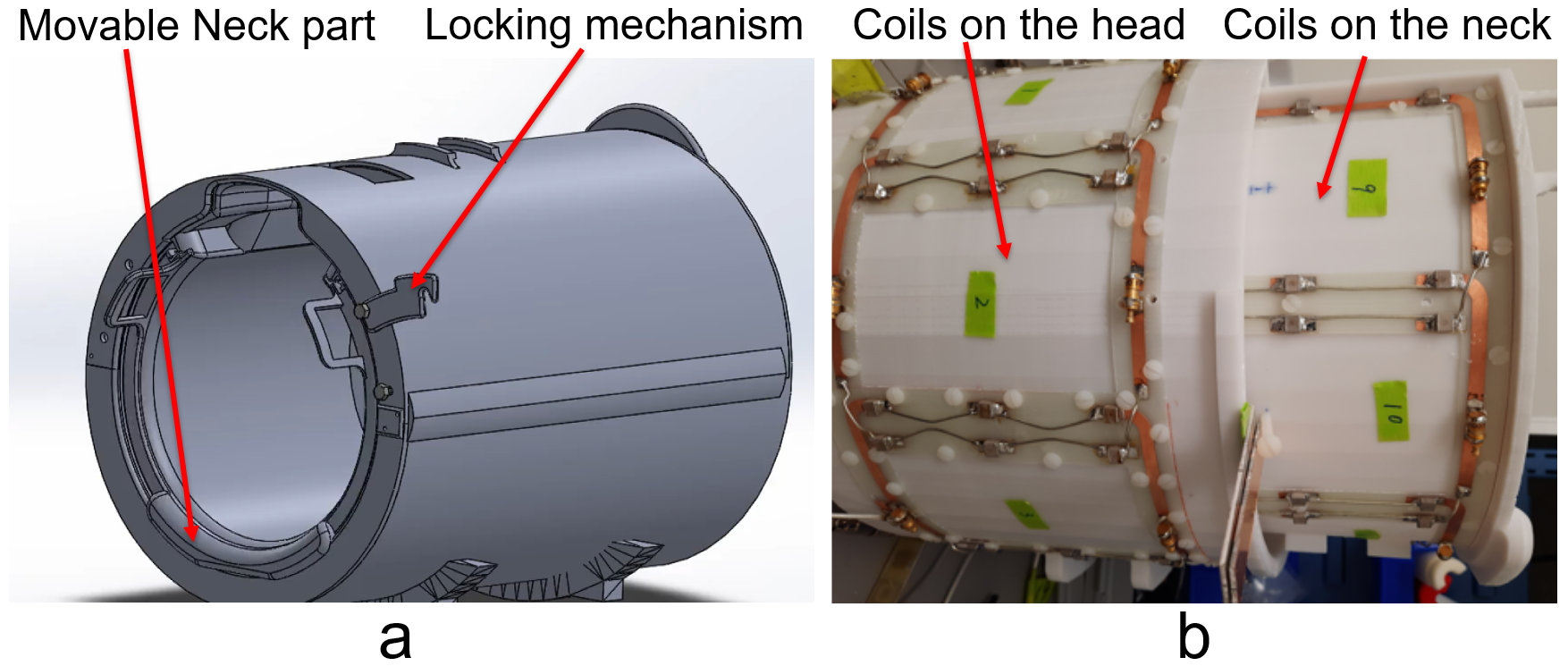
Coil Design: The coil frame was 3D printed (Fortus MC450, Stratasys), and the neck part is movable. The inner diameter of the coil frame is 210mm and provides extra space for the nose by a 25mm extrusion. Eight transceiver coil elements are distributed around the head sitting on a cylinder with a diameter of 260mm, and a length of 200mm along the z direction. There is 17mm-thick hollow ring formed (the frame is 4mm in thickness). The neck part is an 290° 220mm-diameter and 200mm-long arc hidden within the ring and pulled out by 100mm after positioning the subject on the patient table. An 80mm-long extrude were printed at one end (away from the subject) of the neck part to support the head. A locking mechanism was implemented to fix the position of the neck part so that the coil elements on the neck part are geometrically decoupled from their adjacent counterparts on the head part. Figure 1 shows the coil housing and coil layout in the array. The coil elements are 105.8mm in xy plane and 125mm in z direction on the head and 94mm in xy plane and 125mm in z direction on the neck. The copper width of the coil element was 6mm. One 1:8 power splitter that evenly splits power with 45-degree phase steps between neighboring elements was connect to the 8 coil elements on the head to create a CP combination; another 1:8 power splitter with 45-degree phase steps was connected to the 6 coil elements arranged around the neck and the 2 butterflies on the dome of the head. An extra coax whose length equal to 45 degree was added to quadratically drive the 2 butterfly coil elements on the dome. 16 T/R switches were used to switch the array between the transmit and receive modes. The array was connected to a Philips 7T whole-body MRI scanner via the Nova dual transmit interface and 16ch receive interface boxes (Philips healthcare). Experiments: Human subject studies were performed following a protocol approved by our institutional review board, and informed consent was obtained from the subject. Safety testing and SAR parameters were acquired by following the guidelines for worst-case SAR in (1). Two power amplifiers in the system were used to drive the two 1:8 power amplifiers with equal power, the phase relationship of the power amplifiers was calibrated with a head and neck phantom (εr=60.5, σ=0.45 S/m) by stepping 15 degree per each scan. Dual-TR method (2) was used to acquire the flip angle maps in the experiment. In vivo sagittal GRE images of the head and cervical spinal cord were acquired with a 3D Fast Field Echo (FFE) (3). In vivo T2 weighted images of the cervical spinal cord were acquired with a 3D FFE sequence in sagittal and axial planes respectively.Results and Discussion
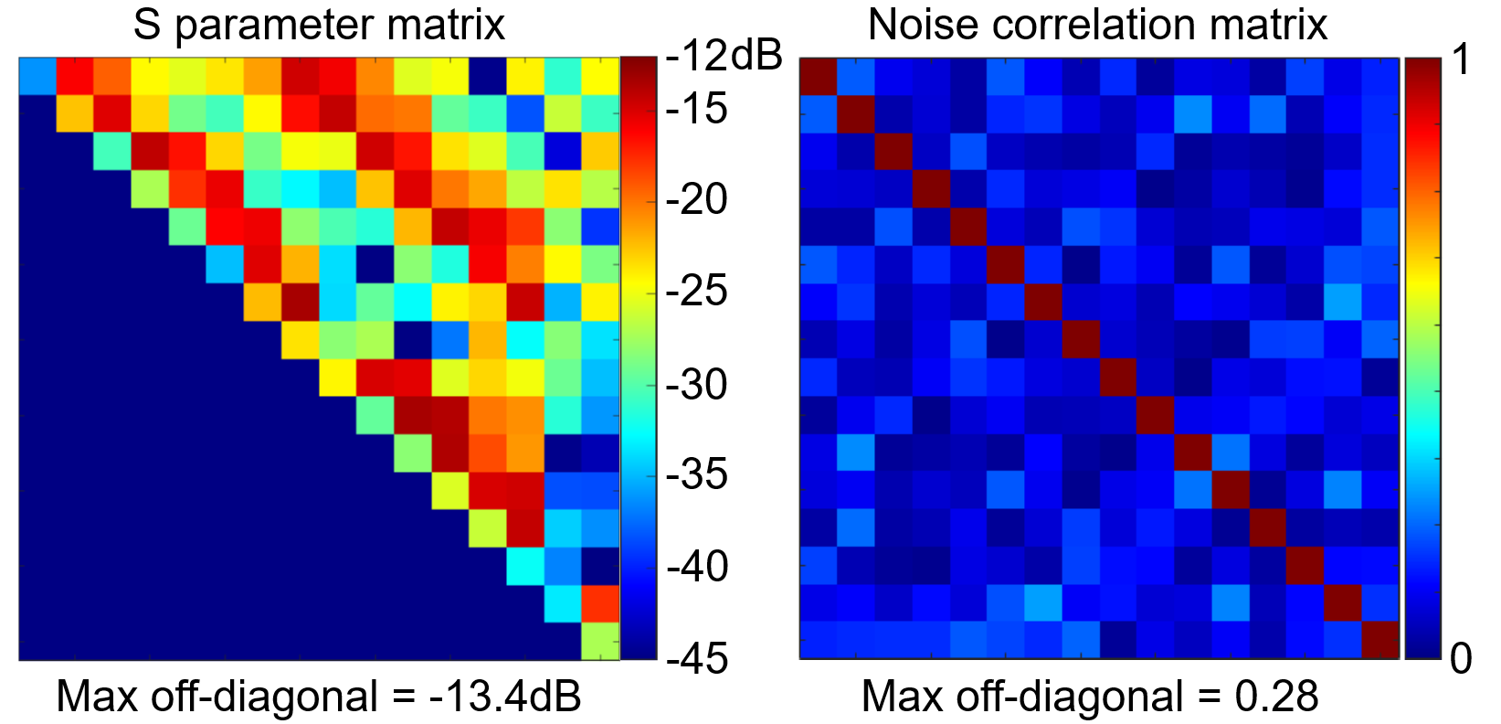
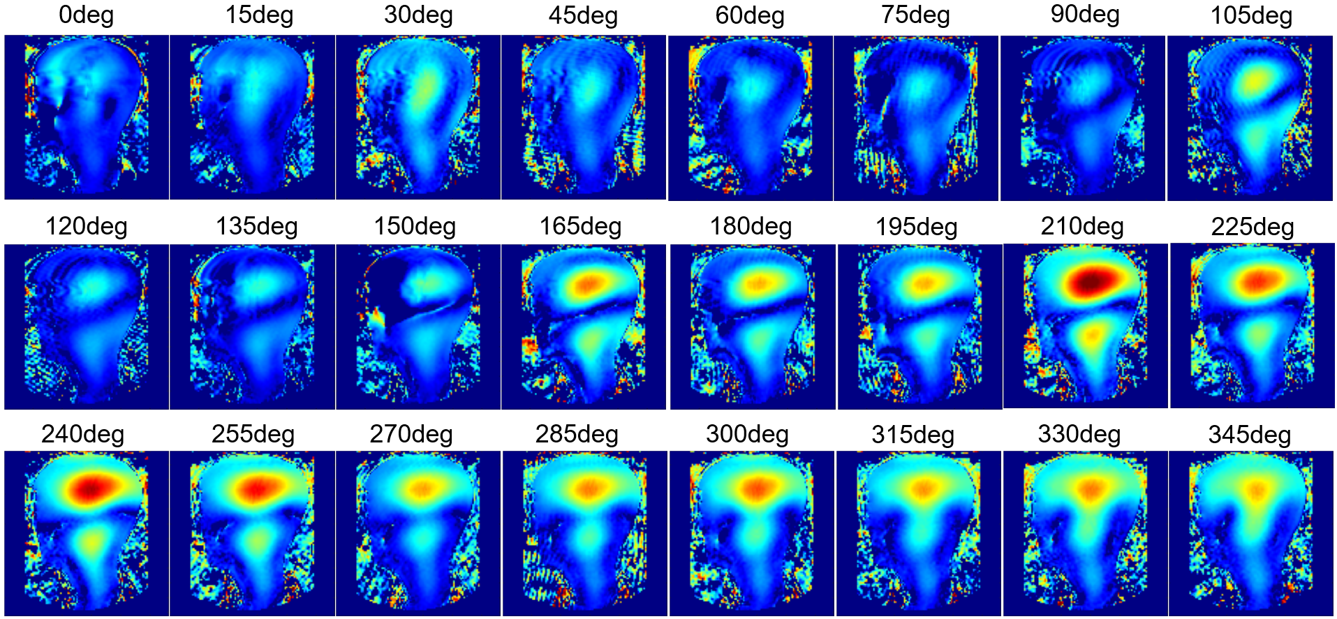
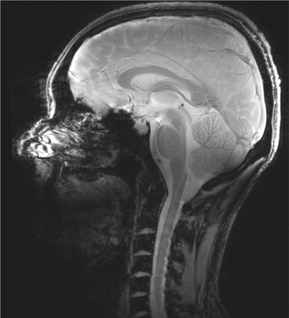
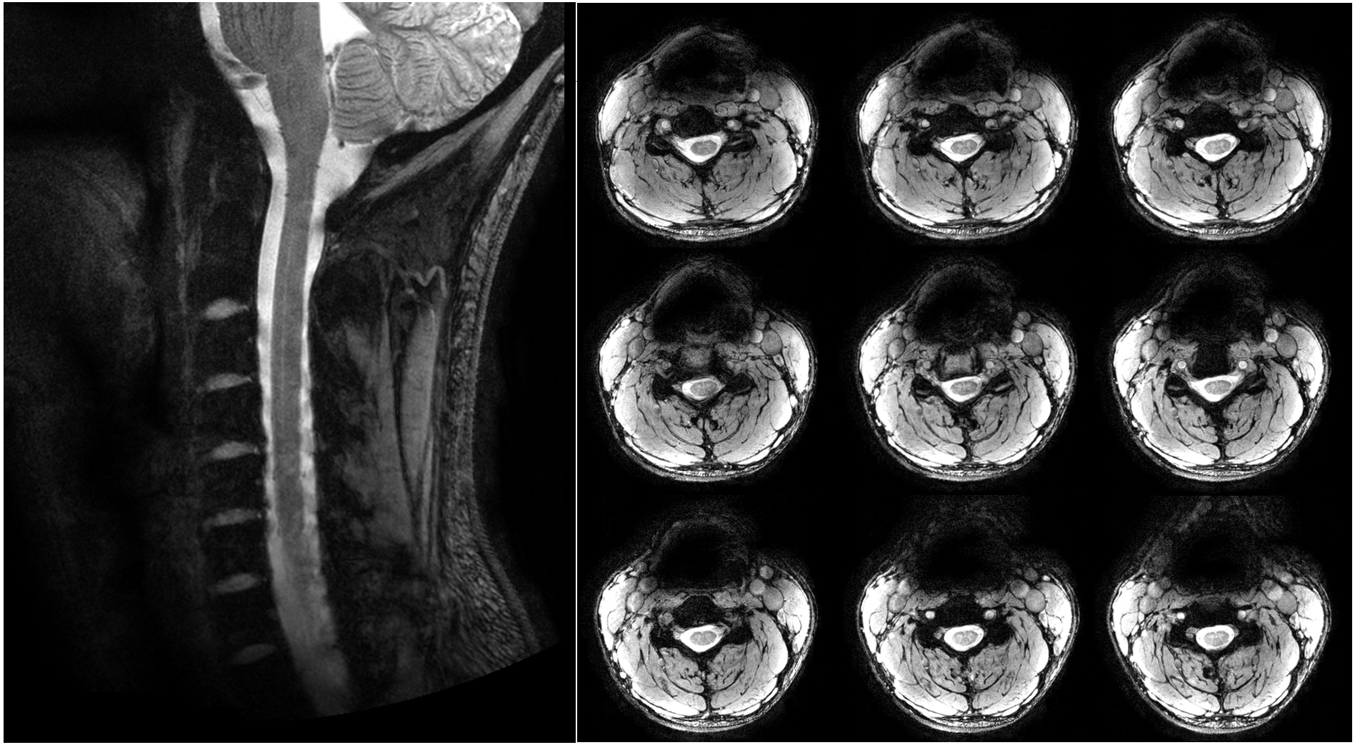
The ratio of unloaded-to-loaded quality factor of a single coil element is 8.31 on the head and 5.74 on the neck, the S parameter matrix of the 16 coil elements on workbench and the noise correlation matrix ARE shown in Figure 2, and the S21 is lower than -13.4 dB for all adjacent coil elements, and the off-diagonal elements of the experimental noise correlation matrix is less than 0.28. Figure 3 shows the flip angle map with different phase relationship between the two power amplifiers. We used the phase relationship of 330-degree relationship between the two power amplifiers for our in vivo scans. Please note that the 330-degree phase difference is between the 2 power amplifiers in the scanner, after considering the extra 90 degree phase in the Nova dual interface box, as well as the cable length difference between the connections of the 2 1:8 power splitters and the coil elements. Figure 4 shows the in vivo GRE image in sagittal plane, from which we can see that the array has a good coverage of the head and the cervical spinal cord. Figure 5 shows an in-vivo in-plane high resolution T2-weighted image of the cervical spinal cord in the sagittal plane (left) and the axial plane (right); these images show good grey and white matter contrast in the cervical spinal cord.Conclusion
Our 7T 16 channel transceiver array provides a longitudinal coverage of both head and cervical spine cord and is capable of simultaneous and high-resolution head and cervical spine cord imaging. Thus the herein presented RF coil design overcomes the severe limitation of currently available commercial 7T head coil designs.Acknowledgements
This work was funded by Cancer Prevention and Research Institute of Texas (CPRIT) RR180056, and was performed under the rubric of the Advanced Imaging Research Center, UT Southwestern Medical Center.References
1. Hoffmann J, Henning A, Giapitzakis IA, Scheffler K, Shajan G, Pohmann R, Avdievich NI. Safety testing and operational procedures for self-developed radiofrequency coils. NMR Biomed 2016;29(9):1131-1144. 2. Voigt T, Nehrke K, Doessel O, Katscher U. T1 corrected B1 mapping using multi-TR gradient echo sequences. Magn Reson Med 2010;64(3):725-733.
3. van der Meulen P, Groen JP, Tinus AM, Bruntink G. Fast Field Echo imaging: an overview and contrast calculations. Magn Reson Imaging 1988;6(4):355-368.
Figures