4109
A 16-channel splittable non-overlapped self-decoupled loop transmitter for 10.5 Tesla human head imaging1University of Minnesota, Minneapolis, MN, United States
Synopsis
A 16-channel dual row loop transmitter utilizing self-decoupling principles has been designed and prototyped for human head imaging at 10.5 Tesla. The coil employs an intentional asymmetry of impedances within each coil element in order to reduce the interaction between coil elements. Electromagnetic simulations provide an estimate for achievable decoupling and the expected loop current distribution with both a phantom load and a human head model. Bench measurements confirmed the simulation results and indicated coil to coil decoupling on the order of -10 dB or better. MR experimental results indicated minimal interaction with our 63 channel receiver array.
Summary of Main Findings
A 16-channel dual row loop transmitter utilizing self-decoupling principles has been designed and prototyped for human head imaging at 10.5 Tesla. Bench measurements confirmed the simulation results, and MR experimental results show a promising future.Introduction
At Ultra High Fields (UHF) such as 10.5 Tesla (T) the importance of parallel transmission techniques and high channel count transmitter arrays capable of independent field generation has been well documented. One main challenge in the design and construction of UHF transmit arrays is finding an efficient array element decoupling strategy. Recently Yan et al introduced a novel decoupling technique, which allows for non-overlapped decoupling of neighboring elements and achieves ‘self-decoupling’ through manipulation of the coil current distribution1. The underlying principle for this decoupling technique is the utilization of ‘loopole’-type2 uneven coil current distributions for loop coils, which is easier to achieve with increased operating frequency since the loop dimensions approach the wavelength3. Tavaf et al took advantage of this and combined self-decoupling principles with preamplifier decoupling for 32 and 64-channel 10.5 Treceiver arrays3,4. Those arrays were built with a combination of non-overlapped neighboring loops within each row, and geometrical overlaps of neighboring loops between rows. Sappo et al recently extended this and presented a 30-channel triple row loop transmitter for 7 T5,6. Here we take our previous overall layout7 one step further by first evaluating in Electromagnetic (EM) simulation and then building for 10.5T an entirely non-overlapped dual row 16-channel self-decoupled loop transmitter without the use of decoupling transformers. This new self-decoupled layout significantly simplifies EM co-simulations, which reduces the development time from concept to construction.Methods
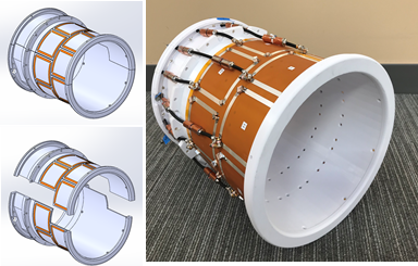
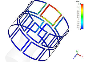
The 16-channel transmit array was laid out in a dual row arrangement mounted on a 28.5 cm ID cylindrical former (see Fig. 1). Each of the two rows contained eight square loops measuring 10x10 cm. The two rows were offset from one another, with the inferior row having a 22.5 degree azimuthal rotation (around the z-axis) compared to the superior row. There is a gap of 1 cm between neighboring loops as well as the two different rows (along the z-axis). This coil arrangement replicates our previous 10.5 T transformer-decoupled transmit array7. The coil former was designed and 3D printed (Fusion3 F410, Greensboro, NC, USA) in-house using PETG filament. All feed circuits were equipped with coaxial cable traps8. Cabling to the inferior row was routed along the superior row’s coil centerlines to minimize interaction (Fig. 1); these cable traps attenuate common-mode currents and reduce induced currents from the transmitter elements. The array circuit artwork was fabricated (PCBWay, Shenzhen, China) with 35 µm copper conductors etched onto a flexible polyimide substrate. Individual coil tuning and matching was achieved with both fixed (KYOCERA AVX, Fountain Inn, SC, USA) and variable (Sprague Goodman, Westbury, NY, USA) capacitors. CST Studio Suite (Dassault Systèmes Simulia Corp., Johnston, RI) was used to produce EM simulations (Fig. 2,3) over a frequency range of 1 GHz using the finite integration technique to solve Maxwell’s equations following the methodology described previously7.Results and Discussion
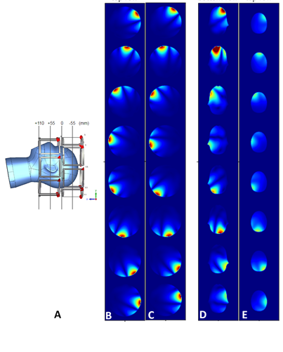
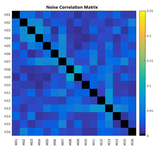
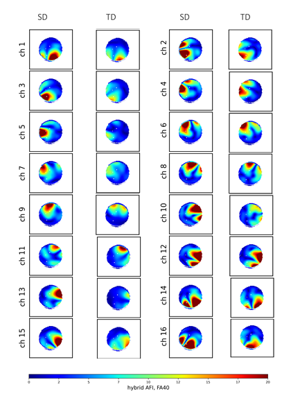
Our bench measurements demonstrated good coil tuning and matching to both a phantom load and human head, with and without our 10.5 T 63-channel receive array insert. The average coil-to-coil decoupling was -25.9 dB, with a worst case instance of ~-10 dB; this was sufficient to tune and match each coil element to an average of ~-33.9 dB at 447 MHz, the 1H Larmor frequency at 10.5T. With MR experiments, we observed an excellent noise correlation between the array elements (Fig. 4), validating our bench measurements. Additionally, the self-decoupled (SD) transmit array demonstrated improved B1 penetration and efficiency per unit power (Fig. 5), compared to our previous transmit array of the same dimensions, which utilized evenly distributed capacitances and transformer decoupling (TD)7,9. These results are consistent with findings reported in Lakshmanan’s 2020 publication, which describes the ‘loopole’-type coil current pattern with more dipole-like characteristics. Importantly the self-decoupling layout significantly reduces the number of co-simulation ports by for EM simulations ~5-fold, which speeds up simulation time and reduces the co-simulation solution space. Importantly this non-overlapped design immediately supports splittable housing designs with no electrical contacts, making it easier to position subjects, and thus increasing the available subject population in a variety of medical research applications.Acknowledgements
This research was funded by NIH U01 EB025144, BTRC P41 EB027061, P30 NS076408, NIH S10 RR029672 grants.References
1. Yan, X., Gore, J. C. & Grissom, W. A. Self-decoupled radiofrequency coils for magnetic resonance imaging. (2018) Nat Commun 9, 3481.
2. Lakshmanan, K., Cloos, M., Brown, R., Lattanzi, R., Sodickson, D. K. & Wiggins, G. C. The "Loopole" Antenna: A Hybrid Coil Combining Loop and Electric Dipole Properties for Ultra-High-Field MRI. (2020) Concepts Magn Reson Part B Magn Reson Eng 2020.
3. Tavaf, N., Lagore, R. L., Jungst, S., Gunamony, S., Radder, J., Grant, A., Moeller, S., Auerbach, E., Ugurbil, K., Adriany, G. & Van de Moortele, P. F. A self-decoupled 32-channel receive array for human-brain MRI at 10.5 T. (2021) Magn Reson Med 86, 1759-1772.
4. Tavaf, N., Radder, J., Lagore, R. L., Jungst, S., Grant, A., Ugurbil, K., Adriany, G. & Moortele, P. F. V. d. Designing a Self-Decoupled 16 Channel Transmitter for Human Brain Magnetic Resonance Imaging at 447MHz. (https://arxiv.org/abs/2103.07516, 2021).
5. Sappo, C., Drake, G., Yan, X. & Grissom, W. A 30-element transmit array for 7 Tesla brain imaging with array compressed parallel transmission. (2021) Proc Intl Soc Mag Reson Med 29 1, 1426.
6. Lu, M., Gore, J. C. & Yan, X. Optimization of a massive-element self-decoupled transmit array for 7T head imaging in Proc Intl Soc Mag Reson Med 29. 1424.
7. Adriany, G., Radder, J., Tavaf, N., Lagore, R., Jungst, S., Woo, M. K., Grant, A., Eryaman, Y., B, Z., Gunamony, S., Lattanzi, R., K., U. & Van de Moortele, P. F. Evaluation of a 16-Channel Transmitter for Head Imaging at 10.5T in 2019 International Conference on Electromagnetics in Advanced Applications (ICEAA). 1171-1174 (IEEE).
8. Terman, F. Radioengineer’s Handbook. (Mc Graw Hill, 1943).
9. Shajan, G., Kozlov, M., Hoffmann, J., Turner, R., Scheffler, K. & Pohmann, R. A 16-channel dual-row transmit array in combination with a 31-element receive array for human brain imaging at 9.4 T. (2014) Magn Reson Med 71, 870-879.
Figures