4107
A 24-channel vacuum formed pediatric pTx knee coil for 7T
Matt Waks1, Karthik Gopalan2, Stefan Zbyn1, Lance DelaBarre1, Abdul Wahed Kajabi1, Julian Maravilla2, Gregor Adriany1, Michael (Miki) Lustig2, Ana Claudia Arias2, and Jutta Ellermann1
1University of Minnesota, Minneapolis, MN, United States, 2UC Berkely, Berkeley, CA, United States
1University of Minnesota, Minneapolis, MN, United States, 2UC Berkely, Berkeley, CA, United States
Synopsis
A pediatric focused 24-channel prototype pTx 7T knee coil consisting of an 8 channel stripline transceiver and a 16-channel close fitting receiver array is described. Initial comparison with an adult size knee coil indicates peripheral SNR gains and more modest - yet notable- gains for central SNR due to the favorable filling factor and form fitting receivers of the pediatric knee coil prototype.
Introduction
Although the knee is the most commonly MRI-imaged joint in the pediatric population, there is to date no dedicated pediatric knee coil commercially available. Thus, possible SNR gains and fast imaging with parallel acquisition methods are not fully realized due to the increased distance between the pediatric knee and receive arrays in the adult-size knee coils. Here we attempt to address this issue and present a dedicated pediatric knee coil array for use at 7 Tesla.Materials and Methods
The coil combines 16 close fitting receive-only array elements with an 8-channel pTx stripline transceiver array for a combined 8-channel transmit / 24-channel receive 7 T Knee Array (Fig. 1). The eight-channel anterior receive array was built using a previously described vacuum-formed coil building technique1,2. Briefly, the conformal array was built by patterning traces on a flat polycarbonate sheet. The sheet was then vacuum formed onto a mold of a knee and the traces were made conductive with electroless copper plating (Fig. 2). After populating the traces with RF components, the form-fitting printed array (~ 12 cm x 7 cm ea.) was combined with an 8-channel posterior receive array which was integrated into the lower knee coil housing. The eight posterior receive coils were arranged in three rows along the Z-axis, (with 3-2-3 coil elements per row) to maximize the parallel imaging opportunities given the 8-channel limit of the system connector. Six of the posterior elements (3 in the superior, and 3 in the inferior rows) were circular loops with diameter of 5 cm, while the middle row consisted of two elliptically shaped loops with major diameter of ~7.6 cm, and a minor diameter of 5 cm. All receive array elements (both anterior and posterior) were connected to a low-input impedance preamplifier (WanTcom, Chanhassen, MN, USA) to take advantage of preamplifier decoupling, as well as being overlapped with neighboring loops for geometric decoupling. The 8-channel transmit array (which can also be used as a transceiver array) consisted of 8 independently-shielded stripline elements, equally split between the anterior and posterior housings. These 8 stripline elements were capacitively-shortened using fixed chip capacitors (KYOCERA AVX, Fountain Inn, SC, USA), and mounted on a 23.5 cm diameter former. Each element had a 12.5 mm wide central conductor separated from a copper shield by a polytetrafluoroethylene (PTFE) dielectric. Each of the stripline elements was tuned, matched, and decoupled with variable capacitors (Knowles/Voltronics, Denville , NJ, USA) to both a knee-shaped phantom load, as well as a human knee. The stripline elements were capacitively decoupled to -13.7 dB or better to the knee-shaped loading phantom, while the human knee presents a larger load to the coil and thus increases the transceiver element decoupling. The complete knee coil assembly was made up of three major subassemblies: the anterior, containing four stripline transceiver elements; the posterior, containing four stripline transceiver elements and 8 receiver elements; and the previously published 8-channel receiver insert [1,2]. The anterior and posterior housings were designed and 3D printed (Fusion3 F410, Greensboro, NC, USA) in-house using PETG filament, while the 8-channel receiver insert was vacuum formed [1,2]. The anterior and posterior housings formed a flared inner diameter of ~22, ~16.5, and ~17.5 cm as measured along the z-axis. The performance of the newly developed pediatric knee coil prototype was compared to the commercially available 16 cm i.d. 7T industry standard knee coil (birdcage transmitter and 28-channel receive array). To evaluate the expected SNR gains of the close-fitting receive arrays in the pediatric knee coil, a 3D-printed knee phantom was placed 7 mm above the bottom of the coil and scanned with both coils at 7T (Siemens Healthineers, Erlangen, Germany). The shape of the 11 cm long phantom was based on an MRI of a 17-year-old and the phantom was filled with 100 mM saline and 4 mM CuSO4. A fully-relaxed gradient echo image was reconstructed in SNR units [3] and corrected by flip angle maps[4] to simulate the SNR of a homogenous excitation[5]. The volunteer study was approved by the institutional review board and informed consent was obtained.Results and Discussion
Contribution of individual stripline transceiver elements (S1 to S8) and of the vacuum formed receiver insert (RX1 to RX8) were acquired (Fig. 3). Since the phantom is located close to the bottom of the coils, both coils have good posterior SNR (Fig. 4). The close proximity of the vacuum-formed array significantly increases peripheral SNR and the nearly 100% filling-factor contributes additionally to a 39% increase in central SNR. Though we designed our initial prototype conformal receive array for older adolescents, we plan to build numerous sizes of the vacuum formed arrays to cover the full pediatric population. In future work we also plan to explore multi-row arrangements of the anterior array for further improved SNR and parallel imaging performance. Not discussed here, we observed extensive longitudinal coverage with our stripline transceivers and associated higher overall RF power requirements, thus we plan in the future to evaluate shielded loop transmitters or dipoles as alternative transceivers.Acknowledgements
This research was funded by NIH, NIAMS RO1 AR070020, NIH BTRC P41 EB027061. The research was partially funded by NIH 1U01EB029427-01 and NIH 1U01EB025162-01. This material is based upon work supported by the National Science Foundation Graduate Research Fellowship under Grant No.(DGE 1752814). Any opinions, findings, and conclusions or recommendations expressed in this material are those of the author(s) and do not necessarily reflect the views of the National Science Foundation.References
1. Gopalan, K., et al. "Vacuum Formed Coils for Magnetic Resonance Imaging." 2021 International Conference on Electromagnetics in Advanced Applications (ICEAA). IEEE, 2021.2. Gopalan, K., et al. “Perfectly Conformal Coils: A Novel Method for Patterning Coils on Complex 3D Surfaces.” Proceedings of the 26th Meeting of the ISMRM, Paris 2018.3. Kellman, P. and E.R. McVeigh, Image reconstruction in SNR units: a general method for SNR measurement. MRM, 2005. 54(6): p. 1439-47.4. Yarnykh, V.L., Actual flip-angle imaging in the pulsed steady state: a method for rapid three-dimensional mapping of the transmitted radiofrequency field. MRM, 2007. 57(1): p. 192-200.5. Adriany, G., et al., Transmit and receive transmission line arrays for 7 Tesla parallel imaging. MRM, 2005. 53(2): p. 434-45.Figures
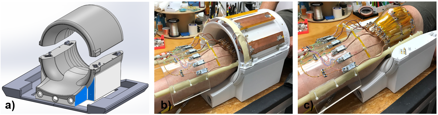
Fig.1: a) Pediatric knee coil housing including the Rx array consisting of 8 loops integrated into the posterior portion of the coil. b) Two elements of the 8-channel stripline transceiver can be seen. c) The vacuum formed Rx array tightly fitted around a knee joint.
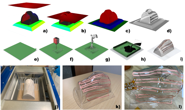
Fig. 2: Conformal receive coil design. a-c) Simulation of the vacuum forming process. d) Distorted coil design mapped onto the 3D surface. e) Polycarbonate sheet masked with polyester tape. f) Predistorted coil pattern cut out of the mask with a CO2 laser. g) Sheet is sandblasted with 100 grit white fused aluminum oxide. h) Exposed areas are catalyzed with palladium-tin solution. i) Mask is removed, sheet is vacuum formed and copper plated. j) Catalyzed plastic sheet loaded into vacuum former. k) 8-ch knee coil traces after copper plating. l) Single channel tuned with rigid capacitors.
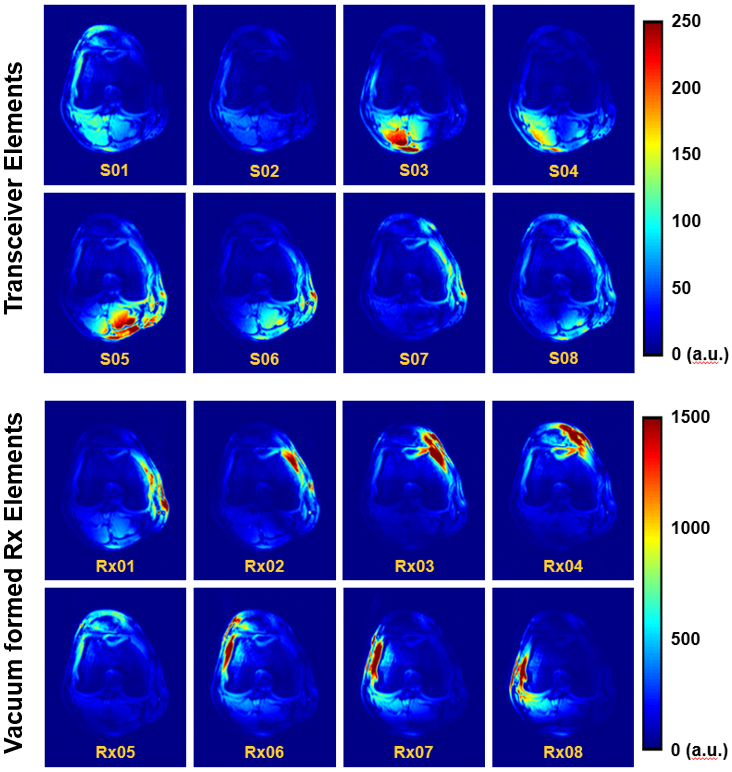
Fig. 3: Contribution of individual receive elements. Stripline elements (top) contribute with much less signal when compared to the elements in the vacuum formed Rx array (bottom) around the knee. Note the difference in scale between top and bottom displays.
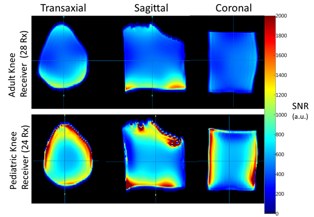
Fig. 4: SNR comparison at 7T of a pediatric-sized knee phantom in a commercially-available single transmit adult-sized knee coil and the newly developed 8-channel pTx pediatric knee coil with a tight-fitting receiver array. The SNR has been corrected for transmit field variations to demonstrate receiver performance independently.
DOI: https://doi.org/10.58530/2022/4107