4105
An 8-Channel High-permittivity Dielectric Material-Coated Half-Wave Dipole Antenna Array for Knee Imaging at 7T1Biomedical Engineering, University at Buffalo, Buffalo, NY, United States
Synopsis
Magnetic resonance imaging for Musculoskeletal imaging plays a vital role in the early detection of various abnormalities. New array systems designed explicitly for Musculoskeletal imaging at Ultra-high field strengths are being developed rapidly. In this study, we propose a new 8-channel array system consisting of High-permittivity dielectric material-coated half-wave dipole antennas for knee imaging at Ultra-high field 7 Tesla.
Introduction
Half-wave dipole antennas provide many advantages over other RF elements, making them ideal for Ultra-high field MRI applications (1). Further, High dielectric constant materials have proven to have a positive effect on the B1 fields (2). They have successfully reduced the Electric fields across coil elements, thereby ensuring safer MRI at Ultra-high field strengths. Dielectric materials can also manipulate dipole length or resonant frequency, yielding a unique way to shorten coil length, which is often too long for in vivo imaging in practice. We propose a new array system consisting of eight dielectric material-coated half-wave dipole antennas with the desired coil length without bending the dipole conductors and compare the results with a conventional half-wave dipole antenna array. We used electromagnetic simulations in COMSOL Multiphysics to analyze the performance of the proposed array system.Method
The proposed array system consists of 8 high dielectric-material coated half-wave dipole antennas closely placed around the Human knee phantom. We designed a human knee phantom to resemble the shape of an actual human knee. The Human knee phantom and dimensions can be seen in Fig.1. The material properties used for the knee phantom are as follows: εr: 40, conductivity: 0.08 s/m, relative permeability: 1. The eight elements used in the array are symmetric and the same size (Fig.2a). We tuned each element at 300MHz by selecting appropriate parameters. The dimensions and the parameters used are as stated in Table.1. Each element was excited using an individual lumped port with 450 phase differences from the neighboring element. The Input power was specified as 1W for each channel. We evaluated B1 field distribution, Electric field distribution, and SAR using Electromagnetic simulations in COMSOL Multiphysics. We further compared the results of the proposed antenna system with an 8-channel conventional half-wave dipole antenna operating at 300MHz. The schematic of the 8-channel conventional half-wave dipole antenna is seen in Fig. 3a, and the dimensions are as stated in Table.1.Results
Fig.2 b. shows the SAR evaluation produced by the proposed 8-channel high dielectric-material coated half-wave dipole antenna. The maximum SAR value produced by the proposed array was found out to be 5.47×10⁻¹⁵ W/kg. On the other hand, an 8-channel conventional half-wave dipole antenna produced a maximum SAR value of 2.74×10⁻¹⁵ W/kg; The SAR evaluation can be seen in Fig.3 b. Further, The B1 field distribution produced by the proposed array is as seen in Fig. 2 c & d. We used a logarithmic scale to display the B1 field distribution using the following expression in COMSOL Multiphysics: 20×log10(emw. normB). Fig. 3 c & d. shows the B1 field distribution produced by the 8-channel conventional dipole antenna array. The proposed array produced more vital B1 fields in the center of the phantom and had more penetrating fields. Finally, Fig.2 e & f. shows the Electric field distribution produced by the proposed 8-channel array, and Fig. 3 e & f. shows the Electric field distribution produced by the 8-channel conventional dipole antenna array.Discussion/Conclusion
In this study, we have successfully designed an 8-channel Dielectric material-coated half-wave dipole antenna array system with desired coil length without bending the conductors. We also analyzed the performance of the proposed array system using electromagnetic simulations and compared it with a conventional dipole antenna array. We conclude that the proposed array system produced higher B1 fields in the imaging area than the conventional dipole antenna array, which will provide a more efficient coil array for signal excitation and reception at 7 Tesla. Although this specific dielectric-coated array produced higher SAR over the regular dipole in the knee phantom, the values are way under the FDA limits accepted values.Acknowledgements
No acknowledgement found.References
(1) A.J. Raaijmakers, O. Ipek, D.W. Klomp, C. Possanzini, P.R. Harvey, J.J. Lagendijk, C.A. van den Berg, Magn. Reson. Med. 66, 1488–1497 (2011)
(2) Wang C, Zhang X. Evaluation of B1+ and E field of RF Resonator with High Dielectric Insert. ISMRM p3054 (2009)
Figures
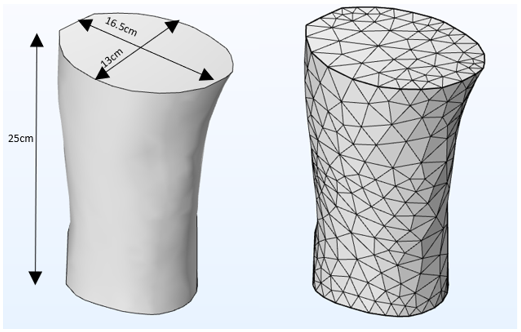
Figure.1 Human Knee phantom (a) Knee phantom with dimensions (b) Mesh of the knee phantom. Material properties: εr: 40, conductivity: 0.08 s/m, relative permeability: 1
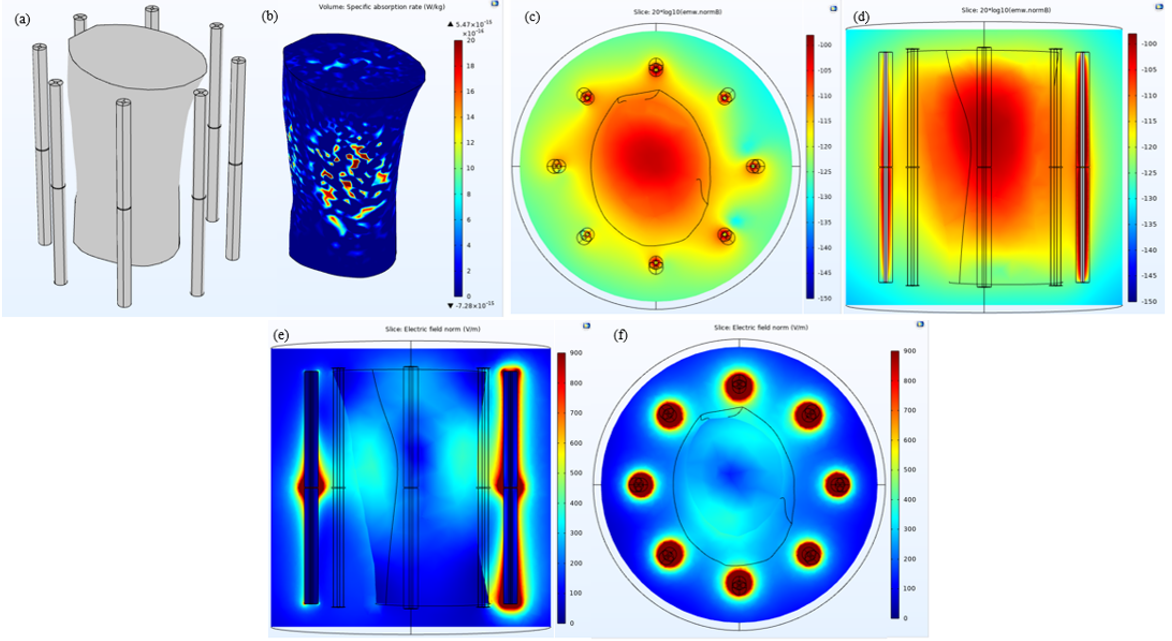
Figure 2. 8-channel Dielectric material-coated half-wave dipole antenna array system (a) 8 Whole-dielectric material-coated half-wave dipole antennas placed around the knee phantom. (b) SAR evaluation. Max. value: 5.47×10⁻¹⁵ W/kg (c) Center axial B1 field distribution (d) Center sagittal B1 field distribution (e) Sagittal electric field distribution (f) Center axial electric field distribution.
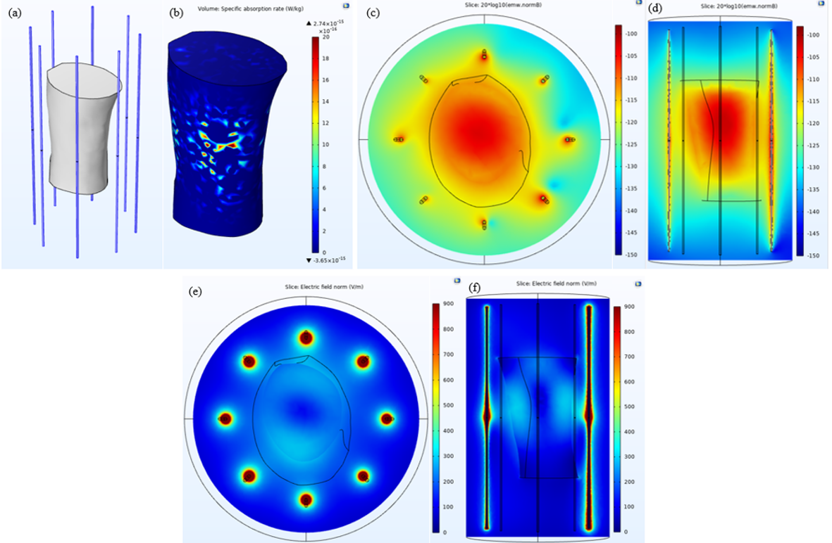
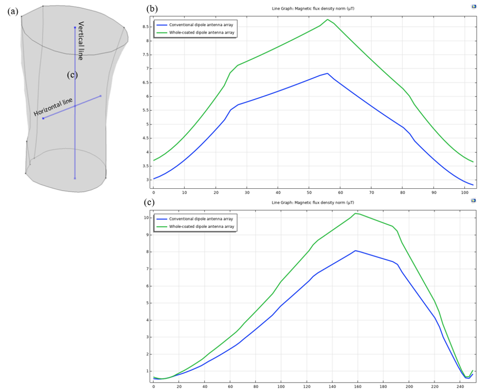
Figure 4.(a) The figure shows the cut-lines used in phantom to plot the 1D profiles. (b) The 1D profile shows the B1 field strength produced along the horizontal line in the phantom by the 8-channel conventional and 8-channel whole-coated dipole antenna array. (c) The 1D profile shows the B1 field strength produced along the vertical line in the phantom by the 8-channel conventional and 8-channel whole-coated dipole antenna array. The 1D profile demonstrates that the whole-coated dipole antenna array produced stronger B1 fields than the conventional dipole antenna array.
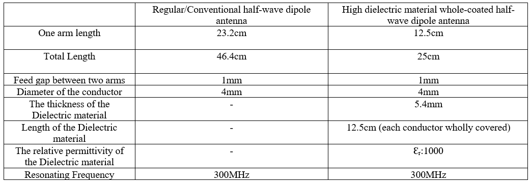
Table 1. The table shows the dimensions and other parameters used for the array elements in the specified array system.