4104
B1 field flattening and length control of half-wave dipole antenna with discrete dielectric coating1Biomedical Engineering, University at Buffalo, Buffalo, NY, United States
Synopsis
This study presents a method for the B1 field flattening and length control of the half-wave dipole antenna for MR imaging with discrete dielectric material coating. To demonstrate this method, we designed a half-wave dipole antenna to operate at 300MHz, including coating the ends of the dipole conductors with a high dielectric material, serving as a way to control the dipole length and electromagnetic field distribution. We also compare the proposed technique with the conventional half-wave dipole antenna and show how the new technique effectively tunes the shorter half-wave dipole antennas at specific frequencies and produces efficient field distributions.
Introduction
The use of half-wave dipole antenna is increasing rapidly in MRI applications. Half-wave dipole antennas have advantages, such as high penetration depth, relatively uniform transmit fields, and better decoupling performance in multichannel arrays, making them ideal for imaging applications. The resonant frequency of the half-wave dipole antenna is determined by its electrical length. The magnetic field distribution strictly follows the half-sine wave pattern, producing a significantly large phase variation, thus dramatical B1 intensity change, along the dipole. It has been challenging to tune shorter half-wave dipole antennas at Ultra-high field strengths such as 7T/300MHz. Previous studies, including meander elements, successfully tuned shorter half-wave dipole antennas at a specific frequency, despite enlarged dipole size, which may show limitations in designing massive coil arrays. Studies also demonstrate that the high dielectric constant materials positively affect the B1 field distributions and have the ability of electric field suppression and frequency tuning. This study incorporates the high dielectric constant materials with discrete coating on the half-wave dipole antenna. It aims to tune shorter half-wave dipole antennas at 300MHz and provide a method to control the dipole length and flatten the B1 field along the dipole at the desired frequency.Method
Three half-wave dipole antenna designs were modeled and simulated to achieve the targeted frequency: a conventional half-wave dipole antenna resonating at 300MHz, and a dielectric material-coated at both the ends of a half-wave dipole antenna. All three designs can be seen in Fig.1,2, & 3. Table.1 below shows the Parameters we used to tune all three antennas. The conventional half-wave dipole antenna was 46.4 cm long to resonate at 300MHz. We aimed to reduce the size to almost half of it and designed another conventional half-wave dipole antenna with a total length of 25 cm. This 25 cm conventional antenna had a resonant frequency of 548MHz. To tune this shorter half-wave dipole antenna at a lower frequency of 300 MHz, we added a high dielectric constant material coating on each end of the conductors. The thickness, length, and relative permittivity of the high dielectric constant material were varied in a parametric sweep, and the parameters at which the antenna resonated at 300MHz were selected. The shorter antenna had a resonant frequency of 300MHz when the thickness of the high dielectric constant material was 7.2 mm, the length of 3 cm, and the relative permittivity of 900. We employed S-parameter evaluation and frequency domain studies to evaluate the field distribution at the resonating frequencies of individual design.Results
The simulation results of all the antenna designs can be seen in fig.1,2, & 3. The maximum electric fields produced over conventional half-wave dipole antenna resonating at 300MHz were 1.54×10⁴ V/m. The 25 cm long conventional half-wave dipole antenna produced maximum electric fields of 1.39×10⁴ V/m. Finally, the maximum electric fields produced across the end-coated half-wave dipole antenna were 1.61×10⁴ V/m. Although in comparison, the end-coated half-wave dipole antenna produced the highest electric field strength, the electric fields were stronger near the ends, and there is a significant reduction in the electric fields across the length of each conductor. Therefore, low electric fields in the imaging area. Further, our new design produces stronger and more uniform fields than the conventional half-wave dipole antenna (888µT vs. 16.6µT).Discussion/Conclusion
In this study, we proposed a new approach to the B1 field flattening and length control of the half-wave dipole antenna, which includes a discrete dielectric material coating on the ends of the dipoles. The Field distributions and the S-parameter plots were evaluated by Electromagnetic simulation using COMSOL Multiphysics Software. We conclude that the proposed approach with discrete dielectric coating effectively tuned the shorter half-wave dipole antennas at specific frequencies, flattened the B1 field along the dipole, reduced the electric fields in the imaging area, and enhanced the B1 field distribution. With the flattened B1 field and length control, the discretely dielectric coated dipole, as a building block, should be advantageous in designing non-array volume coils or multichannel arrays if an appropriate decoupling method is applied.Acknowledgements
No acknowledgement found.References
1. Raaijmakers AJ, Luijten PR, van den Berg CA. Dipole antennas for ultrahigh-field body imaging: a comparison with loop coils. NMR Biomed. 2016 Sep;29(9):1122-30. doi: 10.1002/nbm.3356. Epub 2015 Aug 17. PMID: 26278544.
2. Raaijmakers AJ, Italiaander M, Voogt IJ, Luijten PR, Hoogduin JM, Klomp DW, van den Berg CA. The fractionated dipole antenna: A new antenna for body imaging at 7 Tesla. Magn Reson Med. 2016 Mar;75(3):1366-74. doi: 10.1002/mrm.25596. Epub 2015 May 2. PMID: 25939890.
3. Rupprecht S, Sica CT, Chen W, Lanagan MT, Yang QX. Improvements of transmit efficiency and receive sensitivity with ultrahigh dielectric constant (uHDC) ceramics at 1.5 T and 3 T. Magn Reson Med. 2018;79(5):2842-2851. doi:10.1002/mrm.26943Figures
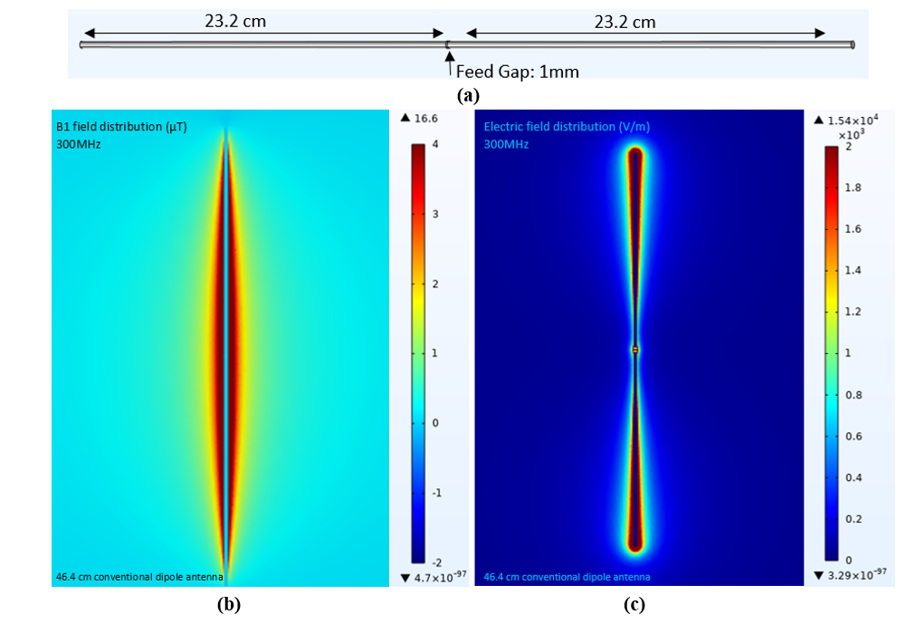
Figure 1. a) Conventional Half-wave Dipole antenna with 46.4cm total length b) B1 Field Distribution, c) Electric Field Distribution.
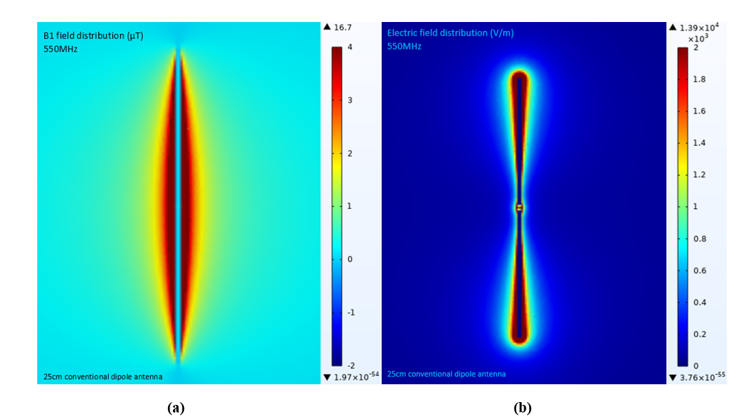
Figure 2. 25 cm long conventional half-wave dipole antenna a) B1 Field Distribution, b) Electric Field Distribution.
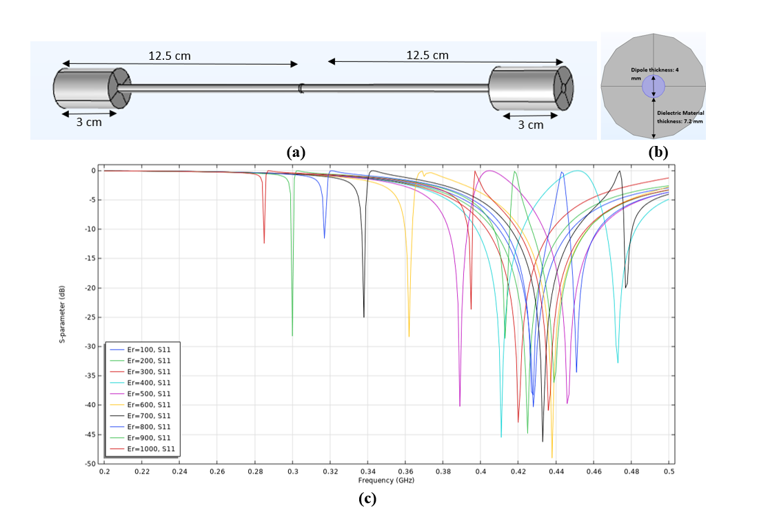
Figure 3. a) End-coated half-wave dipole antenna with 25 cm total length, b) Conductor thickness: 4mm and Dielectric material thickness: 7.2 mm, length of the dielectric material: 3cm c) S-parameter evaluation for different relative permittivity values ranging from 100 to 1000, length of 3cm and thickness of 7.2 mm for the high dielectric material
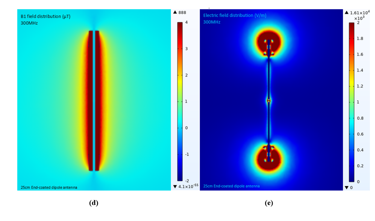
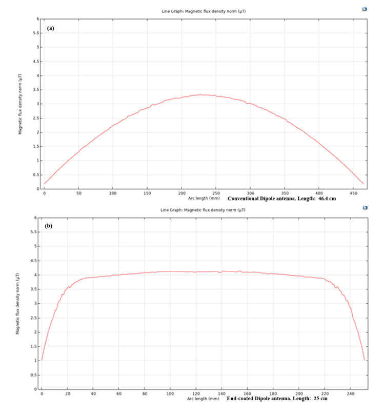
Figure 4. 1D line plots showing magnetic field distribution across the length of the half-wave dipole antenna (a) 46.4 cm conventional half-wave dipole antenna’s magnetic field distribution in µT. (b) 25 cm End-coated half-wave dipole antenna’s magnetic field distribution in µT.
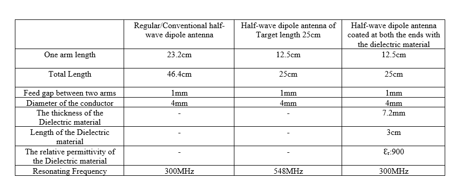
Table 1. The table shows the dimensions and other parameters used for each half-wave dipole antenna design.