4103
A Dielectric Material Coated Half-Wave Dipole antenna for Ultrahigh Field MRI at 7T/300MHz1Biomedical Engineering, University at Buffalo, Buffalo, NY, United States
Synopsis
The potential of half-wave dipole antennas in MRI is primarily recognized. This study presents the dielectric material-coated half-wave dipole antenna design and compares it with the conventional half-wave dipole antenna. The design includes a high dielectric material coating around the length of each conductor. The dipole length primarily determines the resonant frequency of a dipole antenna; therefore, it is difficult to tune small half-wave dipole antennas less than 50 cm at 300MHz. Our design provides a solution to this problem and can tune smaller half-wave dipole antennas at 300MHz without meandering the dipole conductors.
Introduction
The half-wave dipole antennas provide high penetration depth and relatively uniform transmit fields and hence, are one of the favorites in Ultrahigh field MRI. The half-wave dipole antenna consists of two conductors of the same lengths on both sides. The half-wave dipole antenna is fed in the center and produces higher electric field strength on the ends of the half-wave dipole antennas, and the magnetic field is more robust in the center. The electric length of the dipole primarily determines the resonant frequency of the dipole antenna. Therefore, it is challenging to change the dipole length or coil size at a given frequency to meet the need of a specific application. The high-permittivity dielectric materials are known to affect the frequency and electric/magnetic fields of various RF coil elements. In practice, to tune the half-wave dipole antennas at specific frequencies, we can only change the conductors' length and thickness. Hence, for 300MHz/7T applications, the total dipole length can be as long as 50cm. The larger length introduces an issue when the region of interest is too small compared to the dipole length. Hence according to their MR application, it is crucial to resize them based on the region of interest. The Meander elements are one of the approaches to tune small-sized half-wave dipole antennas at specific frequencies. Our study presents a new method that utilizes high dielectric material to tune the smaller half-wave dipole antennas at 300MHz and also enhance the B1 field of the dipole.Method
We modeled three half-wave dipole antenna designs: a conventional half-wave dipole antenna resonating at 300MHz, a conventional half-wave dipole antenna of target length, and a dielectric material-coated half-wave dipole antenna of target length. The conventional half-wave dipole antenna for 300MHz is as shown in Fig 1a. The dimensions for a Conventional half-wave Dipole antenna are as follows: one arm length: 23.2cm, total length:46.4cm, the diameter of the conductor:4mm, feed gap between two arms:1mm. Our goal was to tune a shorter half-wave dipole antenna at 300MHz; hence, we specified our target length as 25 cm. For comparison, we built a conventional half-wave dipole antenna of 25 cm and evaluated the field distributions and the resonant frequency. The dimensions for a 25 cm Conventional half-wave dipole antenna are as follows: one arm length: 12.5cm, total length:25cm, the diameter of the conductor:4mm, feed gap between two arms:1mm. The resonant frequency of the 25 cm antenna was found out to be 548 MHz. Finally, to tune this shorter dipole antenna at 300MHz, we added a dielectric material coating across the length of each conductor. We computed parametric sweep, tried different thicknesses and relative permittivity for the high dielectric material, and chose the best parameters at which the antenna was tuned at 300MHz. The 25 cm dielectric material-coated half-wave dipole antenna can be seen in Fig 3 a, b. The dielectric material-coated half-wave dipole antenna dimensions are as follows: one arm length: 12.5cm, total length:25cm, the diameter of the conductor:4mm, feed gap between two arms:1mm, the thickness of the dielectric material: 5.4mm. The dielectric material used in the "dielectric material-coated half-wave dipole antenna" has the following properties: εr: 1000, conductivity: 0 s/m, relative permeability: 1.Results
The simulation results of the Conventional half-wave dipole antenna tuned at 300MHzHH, a 25 cm Conventional half-wave dipole antenna, and the Dielectric coated half-wave dipole antenna operated at 300MHz are obtained as shown in fig.1,2 &3. The conventional half-wave dipole antenna tuned at 300MHz produced the highest electric fields of 1.54×10⁴ V/m. The 25 cm conventional half-wave dipole antenna produced the highest electric fields of 1.39×10⁴ V/m while the "dielectric material-coated half-wave dipole antenna" produced the highest electric fields of 1.25×10⁴ V/m. Additionally, the "dielectric material-coated half-wave dipole antenna" produced more penetrating and more robust B1 field distribution when compared with the conventional half-wave dipole antenna (135µT vs. 16.6µT)Discussion/Conclusion
In this study, we proposed a new approach that includes using dielectric material-coated dipoles, aiming to control the dipole length at a given frequency and enhance the B1 field of a dipole. The Field distributions and the S-parameter plots were evaluated by Electromagnetic simulation using COMSOL Multiphysics Software. We conclude that the new approach using dielectric material coating effectively tuned the shorter half-wave dipole antennas at specific frequencies, reduced the electric fields, and enhanced the B1 field distribution.Acknowledgements
No acknowledgement found.References
1. Raaijmakers AJ, Luijten PR, van den Berg CA. Dipole antennas for ultrahigh-field body imaging: a comparison with loop coils. NMR Biomed. 2016 Sep;29(9):1122-30. doi: 10.1002/nbm.3356. Epub 2015 Aug 17. PMID: 26278544.
2. Raaijmakers AJ, Italiaander M, Voogt IJ, Luijten PR, Hoogduin JM, Klomp DW, van den Berg CA. The fractionated dipole antenna: A new antenna for body imaging at 7 Tesla. Magn Reson Med. 2016 Mar;75(3):1366-74. doi: 10.1002/mrm.25596. Epub 2015 May 2. PMID: 25939890.
3. Rupprecht S, Sica CT, Chen W, Lanagan MT, Yang QX. Improvements of transmit efficiency and receive sensitivity with ultrahigh dielectric constant (uHDC) ceramics at 1.5 T and 3 T. Magn Reson Med. 2018;79(5):2842-2851. doi:10.1002/mrm.26943Figures
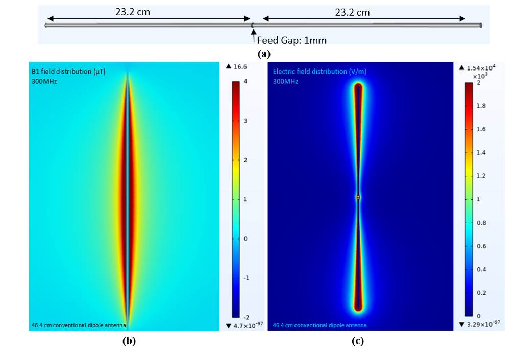
Figure 1. a) Conventional Half-wave Dipole antenna with 46.4cm total length b) B1 Field Distribution, c) Electric Field Distribution.
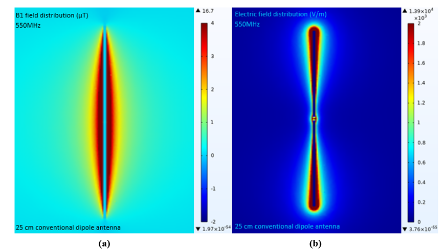
Fig2 25 cm long conventional half-wave dipole antenna a) B1 Field Distribution, b) Electric Field Distribution.
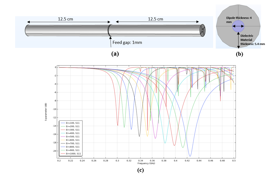
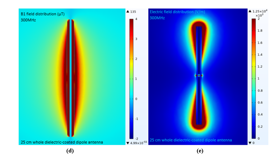
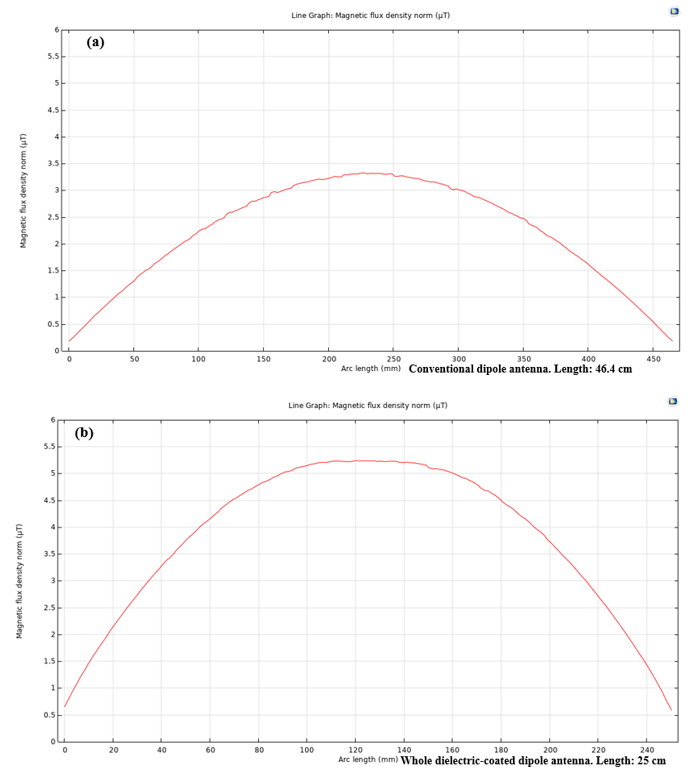
Figure 4. 1D line plots showing magnetic field distribution across the length of the half-wave dipole antenna (a) 46.4 cm conventional half-wave dipole antenna's magnetic field distribution in µT. (b) 25 cm whole-coated half-wave dipole antenna's magnetic field distribution in µT.