4102
Fabrication Methods for Stretchable, Self-tuning Multi-element Liquid Metal Coil Arrays (LiquiTune)1Department of Radiology, Weill Cornell Medicine, New York, NY, United States, 2Department of Radiology and Imaging, Hospital for Special Surgery, New York, NY, United States, 3Pillar of Engineering Product Development, Singapore University of Technology and Design, Singapore, Singapore, 4Department of Biomedical Engineering, National University of Singapore, Singapore, Singapore, 5GE Healthcare, Aurora, OH, United States
Synopsis
We recently proposed a self-tuning stretchable receive coil concept in a single element. Here, we expand the technique to a multi-element array and compare 3 fabrication techniques: 1) single layer, 2) double layer, 3) direct ink writing (DIW). Numerical simulations are used to find the critical overlap for decoupling. In vitro experiments demonstrate almost identical sensitivity between the 3 techniques and between coil elements. DIW is most suitable due to its mechanical stability and thinner/less MR-visible coil elements with a frequency stability of 128+/-0.6 MHz (0 to 30% of stretch) and an SNR improvement of 50% over a commercial coil.
Introduction
The main advantage of liquid metal-based radiofrequency (RF) coils1-6 is the inherent stretchability that is not achievable with conventional conductive materials. We introduced a self-tuning capacitor to improve resonance frequency stability with stretching levels up to 30%6. Here, we expand on the concept by studying the feasibility of an array design by exploring 3 fabrication options: 1) single layer (SL), 2) double layer (DL), and 3) direct ink writing (DIW).Methods
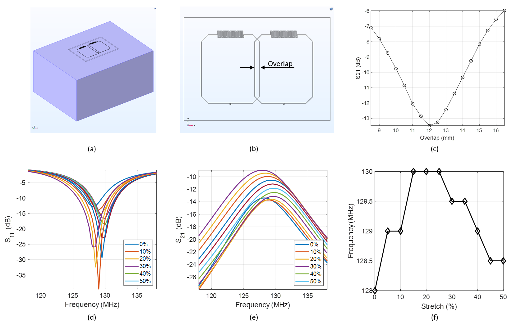
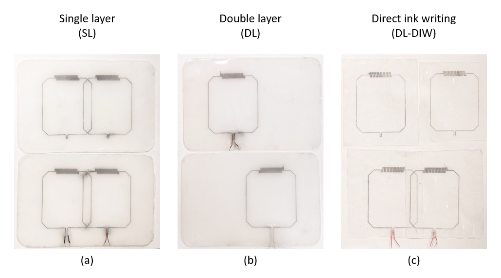
Simulations. The coil geometry uses a 7x6 cm rectangular loop with an integrated interdigital capacitor6. The conducting traces were realized as microchannels of 0.5mm diameter embedded in a polymer substrate. We used critical overlapping to decouple a dual-element array, determined using S21 from simulations (COMSOL): 2 coil elements were positioned on a homogenous phantom (W=22cm, L=33cm, H=16cm, $$$\epsilon_r=78$$$, $$$\sigma=0.46$$$S/m) (Figure 1ab). The critically overlapped dual coil was linearly stretched in x-direction from 0% to 50% and S-parameters were recorded.Fabrication techniques. The original 3D printed molds6 were used in SL (fabrication method 1) and DL (method 2) configurations. The SL coil used jumper wires at the coil overlap (Figure 2a). The DL coil consisted of 2 overlapped coils (Figure 2b). Method 3 involved the fabrication of 2 overlayed coil elements using DIW7 (Figure 2c): DragonSkinTM 30 silicone (Smooth-On) was spin-coated on a glass panel at 700rpm for 40s. Microchannels were printed on a DIW printer (SHOTmini200ΩX, Musashi, Japan) with fast-curing silicone sealant (SpeedSeal) used as a liquid ink. The advantage of DIW is the markedly reduced total thickness of the coil array (0.6mm for DIW compared to 3mm and 6mm for the SL and DL, respectively). For all coils, liquid metal (GaIn) was injected into microchannels and copper wires were inserted at the terminals and connected to a printed circuit board containing tuning, matching, detuning, and preamplifier circuitry.
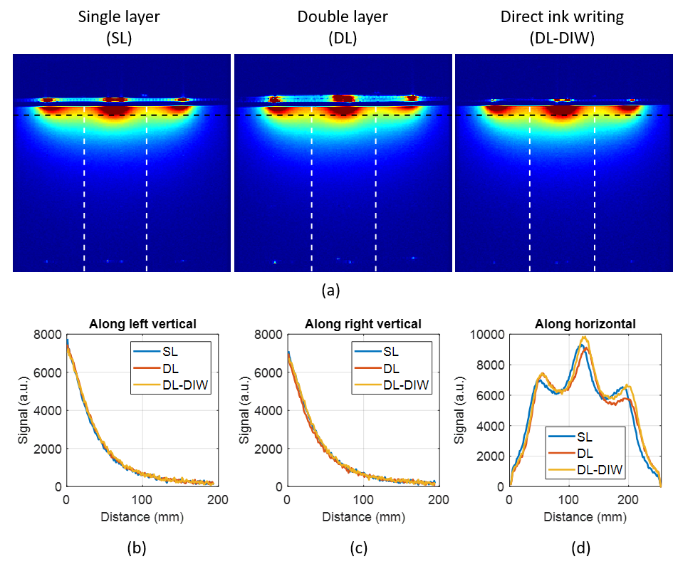
Phantom imaging. Coils were positioned on a standard rectangular silicone phantom (W=22cm, L=33cm, H=16cm) for imaging at 3T (GE Healthcare, MR750). A 3D spoiled gradient echo sequence was used (TR=6.3ms, TE=2.4ms (in phase), FOV=20cm, pixel size 0.8x0.8, FA=12 deg, BW=31.3kHz, slice thickness=1mm, NEX=1).
Stretch tests. All 3 prototypes were tested for mechanical stability when stretched. The most mechanically stable prototype was tested on the bench, in vitro and in vivo. For in vitro imaging, a fast spin echo (FSE) sequence was used (TR=3000ms, TE=13ms(min), FOV=24cm, pixel size 0.9x0.9, ETL=9, BW=15.63kHz, NEX=1, slice thickness=3mm). For in vivo experiments, informed consent was obtained from a healthy volunteer under a locally approved institutional review board protocol. In vivo knee imaging was performed using a FSE sequence (TR=4500ms, TE=8.2ms, FOV=18cm, pixel size 0.4x0.6, ETL=9, BW=83.3kHz, NEX=1, slice thickness=1mm).
Results
Simulations. The S21-parameter simulations revealed a critical overlap distance of 12mm (Figure 1c). Figure 1de show simulated S11 and S21 at different stretching levels from 0% to 50% and demonstrates the relative stability of the coil tuning and good coil decoupling (below -10dB) for stretching levels up to 40%. Figure 2f shows the resonance frequency shift with stretching with a maximum frequency variation of 2MHz.Fabrication techniques. Figure 2 shows the 3 dual-channel coil prototypes fabricated: (a) SL coil without (top) and with (bottom) jumper wires; (b) DL: Two separate identical coils before overlay; (c) Two separate (top) and overlayed (bottom) DIW coils.
Phantom imaging. Figures 3a compares sensitivity (SNR) maps of the 3 coils measured through the central axial slice. Figures 3b-d show the signal measured along three lines, respectively. These images demonstrate that all 3 techniques produce similar sensitivity maps. Without considering mechanical stability under stretch, the DIW technique is favored due to ease and precision of manufacturing and reduced coil visibility due to smaller amounts of polymer used. Anecdotally, we also propose to suppress the appearance of polymer in MR images8.
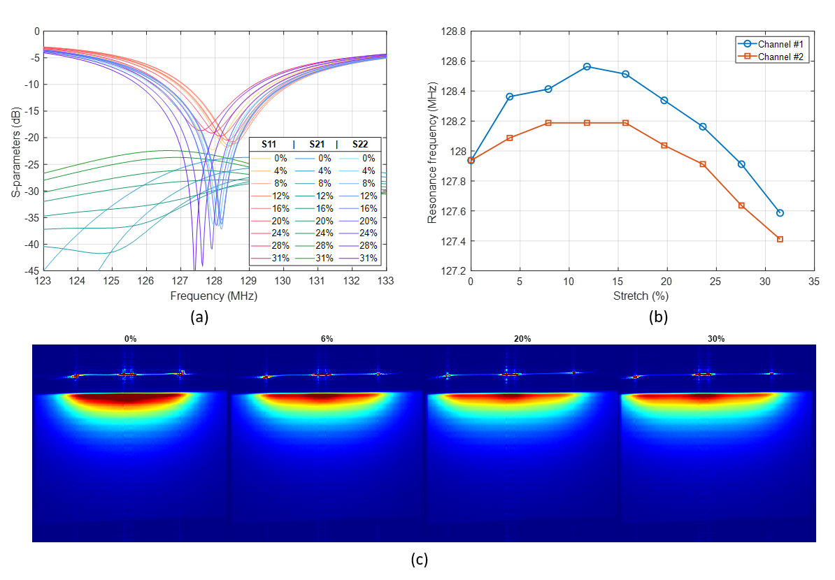
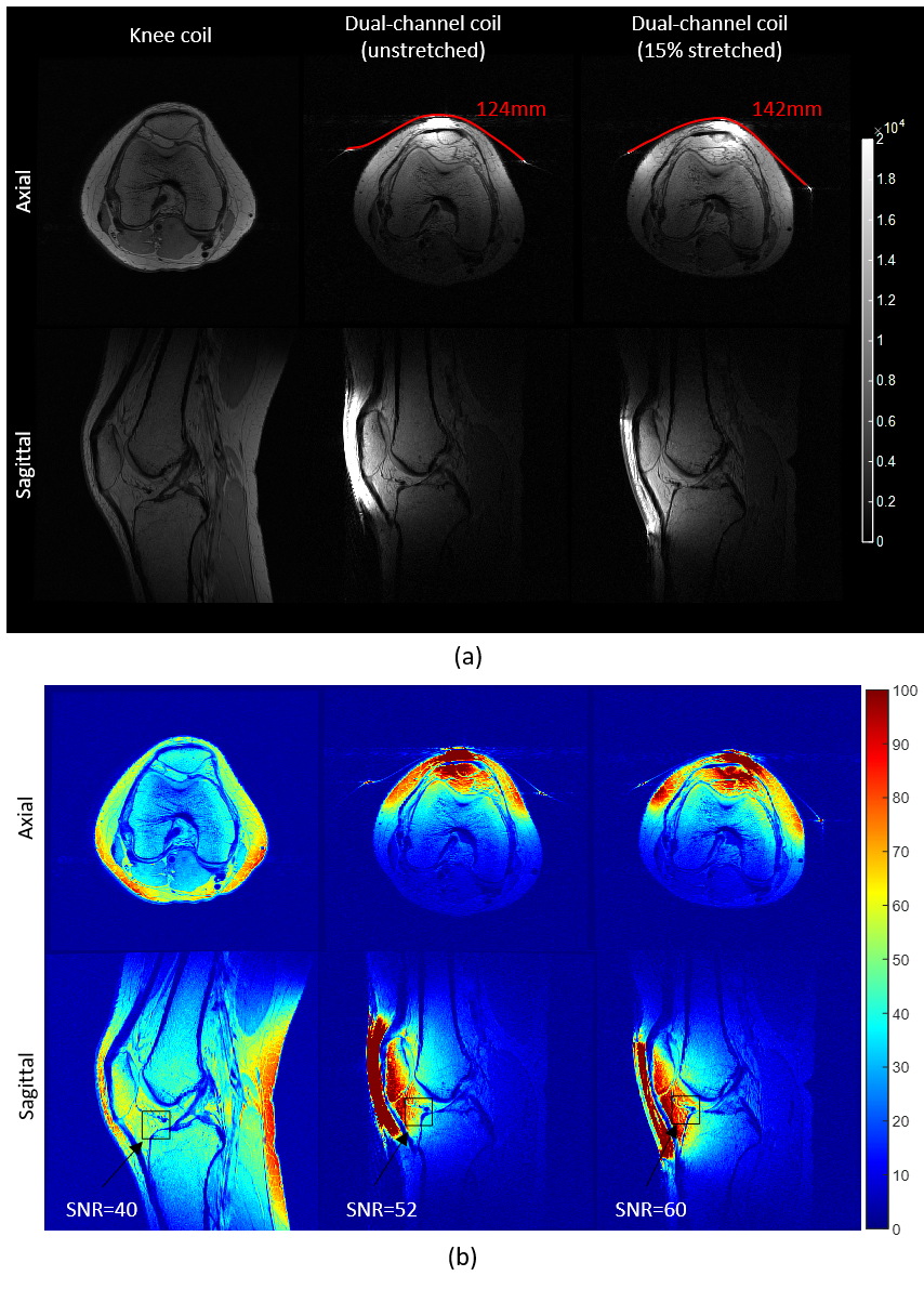
Stretch tests. Both the SL and DL coil prototypes showed mechanical instability – jumpers often broke (SL) and layers separated (DL) in the stretch tests. Thus, we report results for the best performing array, the DIW prototype. (a) Measured S-parameters and (b) resonance frequency shift for degrees of stretch from 0% to 30% showed a measured frequency stability of 128±0.6MHz (Figure 4). Central axial in vitro SNR maps at different stretching levels show an SNR drop of ~10% with 30% stretch, which corresponds to a decrease in SNR~S-3/8 due to an increased coil area S6 (Figure 5c). Central axial and sagittal images of the knee demonstrate higher signal and increased transverse (axial) coverage from the stretched coil (Figure 5a). SNR maps obtained using a commercial knee coil and the DIW prototype in the unstretched and stretched configurations show a 50% SNR improvement in the Hoffa’s fat pad from 40 (commercial coil) to 52 (unstretched) and 60 (stretched) (Figure 5d). The increased in vivo SNR when stretched is attributed to a tighter anatomical fit under tension.
Conclusions
The DIW method is advantageous as it is mechanically stable and produces thinner coils that are less visible on MR images. A frequency stability of 128±0.6MHz and SNR improvement of 50% over a commercial coil was achieved.Acknowledgements
This work was supported by the National Institutes of Health under NIH R00EB024341, and GE Healthcare. The authors would like to acknowledge Muc Chu, Jojo Borja, and Jonathan Dyke of the Citigroup Biomedical Imaging Center for the helpful technical discussions, and Hollis Potter of the Hospital for Special Surgery for the research support of the project.References
1. Varga, M., et al., Adsorbed eutectic GaIn structures on a neoprene foam for stretchable MRI coils. Advanced Materials, 2017. 29(44): p. 1703744.
2. Mehmann, A., et al., On the bending and stretching of liquid metal receive coils for magnetic resonance imaging. IEEE Transactions on Biomedical Engineering, 2018. 66(6): p. 1542-1548.
3. Mehmann, A., et al., Automatic resonance frequency retuning of stretchable liquid metal receive coil for magnetic resonance imaging. IEEE transactions on medical imaging, 2018. 38(6): p. 1420-1426.
4. Port, A., et al., Detector clothes for MRi: A wearable array receiver based on liquid metal in elastic tubes. Scientific Reports, 2020. 10(1): p. 1-10.
5. Port, A., et al., Elastomer coils for wearable MR detection. Magnetic Resonance in Medicine, 2021. 85(5): p. 2882-2891.
6. Motovilova, E., et al., Stretchable self-tuning MRI receive coils based on liquid metal technology (LiquiTune). Scientific reports, 2021. 11(1): p. 1-10.
7. Yamagishi, K., et al., Ultra‐Deformable and Tissue‐Adhesive Liquid Metal Antennas with High Wireless Powering Efficiency. Advanced Materials, 2021: p. 2008062.
8. Motovilova E, et al. Ecoflex+Gd: Rendering Stretchable MR Coils Less Visible. ISMRM2022, submitted.
Figures