4064
Fast 3D T1rho Dispersion MRI with Interleaved Phase Cycling MAPSS1Department of Radiology, Albert Einstein College of Medicine, Bronx, NY, United States, 2Department of Medical Physics, Memorial Sloan Kettering Cancer Center, New York, NY, United States
Synopsis
T1ρ dispersion imaging based on repeated T1ρ measurements at multiple spin-lock frequencies allows characterization of different dynamic processes of tissues. The clinical potential of this techniques is however limited by the total scan time needed to obtain reliable and consistent quantitative measurements. In this work, we propose an unpaired, interleaved phase-cycling scheme for T1ρ dispersion imaging, which almost reduces total scan time by a half compared with the traditional paired PC approach. This method, when combined with other advanced imaging and reconstruction techniques, could potentially enable high-resolution T1rho dispersion imaging acquired within clinically acceptable scan duration.
Introduction
The spin-lattice relaxation time in the rotating frame (T1ρ, and the relaxation rate R1ρ = 1/T1ρ) measured at a single spin-lock frequency (FSL, e.g., 500Hz), has been shown to be sensitive to tissue abnormalities.1 How T1ρ varies as a function of FSL, known as T1ρ dispersion, provides additional information on the functional and dynamic properties of tissue.2-4 A major technical challenge of T1ρ dispersion imaging is the long acquisition time, since multiple quantitative T1ρ mapping experiments are needed at different FSLs. Paired phase cycling (PC) technique has been used to eliminate the signal contaminations from T1 relaxation during the long GRE readout train in a fast MAPSS T1ρ mapping sequence,5 and to minimize the impact of B0/B1 inhomogeneities.6 Paired PC, however, doubles the scan duration for an already long T1ρ mapping sequence. We have presented earlier an unpaired PC strategy for fast T1ρ mapping, which saves 50% scan time, and leads to consistent T1ρ results compared with the traditional paired PC approach.7 In this work, we propose an unpaired, interleaved PC scheme along the FSL direction with only half total scan duration for T1ρ dispersion imaging.Methods
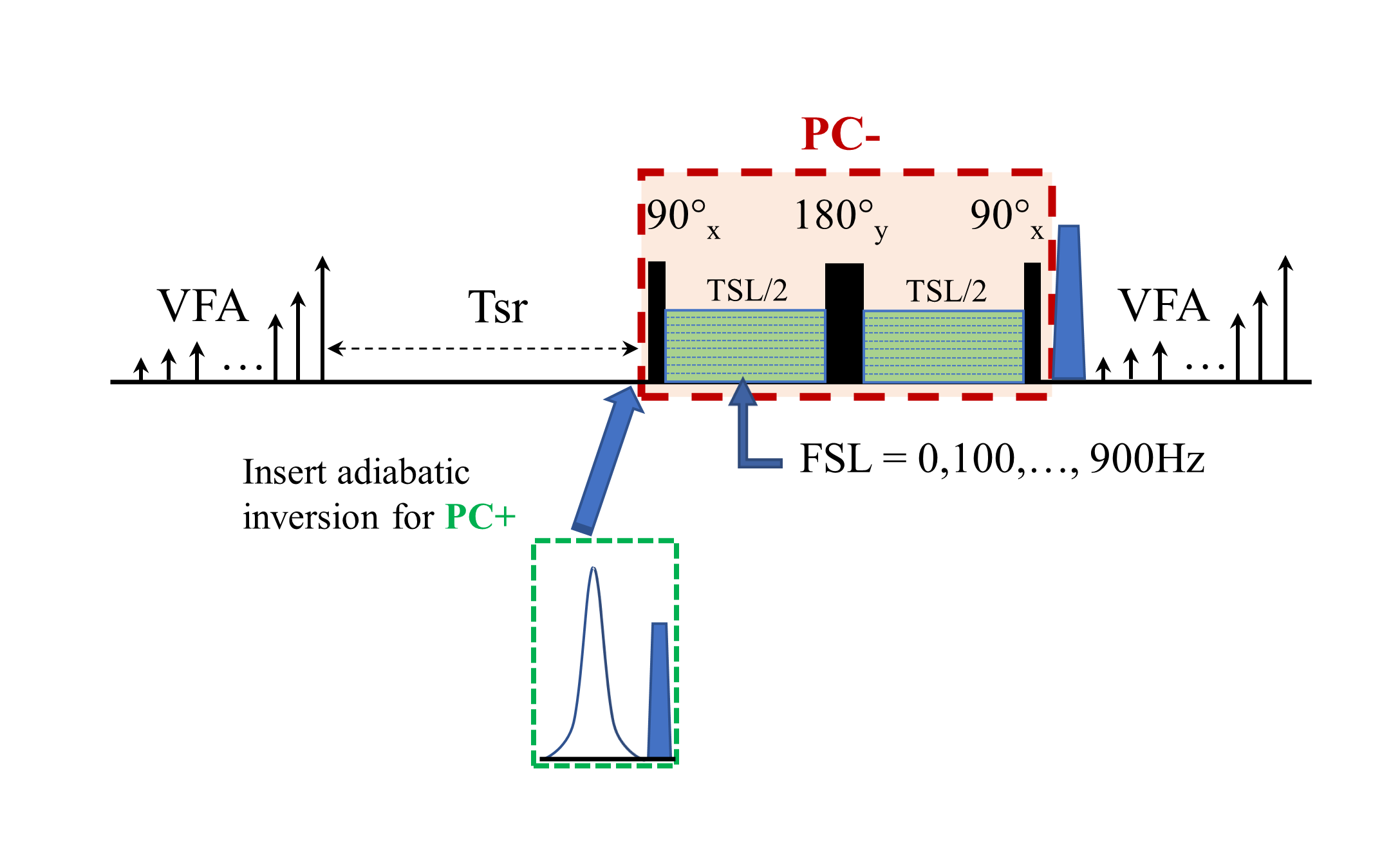
All imaging experiments were performed on a 3T Philips Ingenia MR scanner with a 1ch-TX/16ch-Rx knee coil with maximum B1+ of 27µT. A 3D T1ρ MAPSS sequence was modified to include image acquisitions at multiple different FSLs for T1ρ dispersion imaging on calf muscles of a 46-yr male volunteer (Figure 1).5, 8 The T1ρ preparation module had an RF train of 90°x-TSL/2-180°y-TSL/2-90°x to achieve PC- (-Mz) preparation,9 and the PC+ (+Mz) preparation was obtained by inserting an adiabatic inversion module before the PC- preparation (Figure 1B).10 Ten FSL acquisitions from 0 to 900Hz (100Hz gap) with spin-locking time (TSL) of 30 ms were obtained using an alternation of PC+ and PC-, in addition to the TSL=0ms acquisition. Axial 3D volumetric imaging was performed with the following scan parameters: FOV=140/140/180mm3, acquisition voxel size=1×1×6mm3, TR/TE=5.4/2.6ms, Tsr=1s, compressed SENSE factor=4, and GRE readout train length=96 with centric profile ordering. T1ρ at different FSLs were iteratively reconstructed voxel-by-voxel using a mono-exponential signal model: $$$S^{*}(T_1ρ (FSL±),TSL)=±S_Ae^{-\frac{TSL}{T_1ρ (FSL)}}+S_B,$$$ where SB is the contaminating term originated from T1 recovery,5, 8 and an optimization function of the following: $$$S_A,S_B,T_1ρ (FSL)=\arg min_{S_A,S_B,T_1ρ (FSL)}{\sum||(S(T_1ρ (FSL±),TSL)-S^*(T_1ρ (FSL±) ,TSL)||^{2}+λ·TV(T_1ρ (FSL±))},$$$ where $$$S^{*}(T_1ρ (FSL±),TSL)$$$ and $$$S(T_1ρ (FSL±),TSL)$$$ are the modeled and acquired signals from the TSL acquisitions with positive and negative PC at FSL, λ is the weighting factor for the regularization term, and $$$TV(T_1ρ (FSL±))$$$ is the sum of square of all the differences of the T1ρ values at adjacent FSLs. Three sets of T1ρ maps were generated using the full dataset (FSL_set1), and with only half of the datasets with unpaired, interleaved FSL PC schemes (FSL_sets 2, 3) as detailed in Table 1.Results
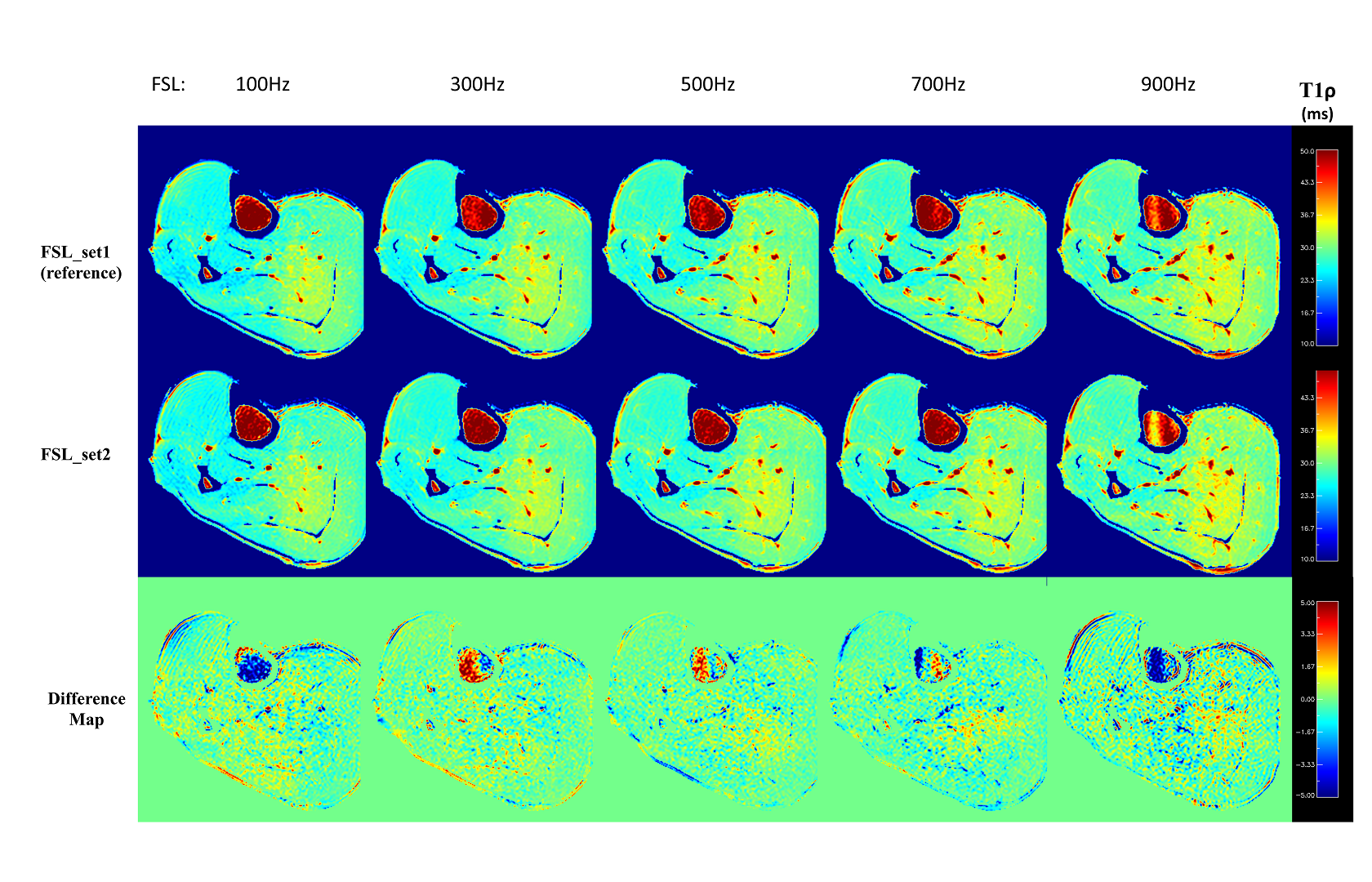
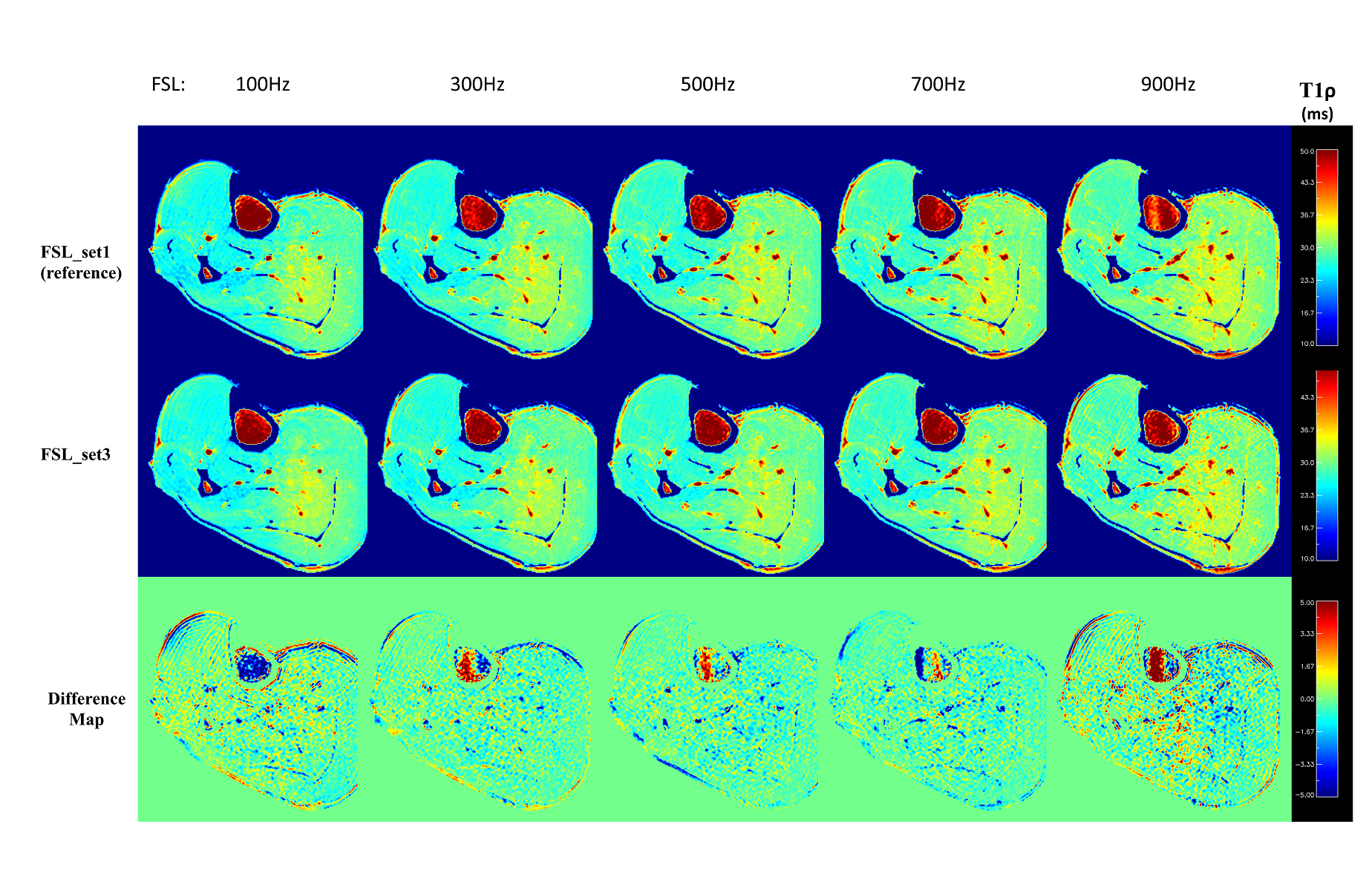
Both FSL_set2 and FSL_set3 resulted in similar T1ρ maps at all FSLs as the corresponding maps from FSL_set1. Figure 2 shows the representative T1ρ maps at different FSLs generated from FSL_set1 (first row) and FSL_set2 (second row). There is little difference between the two methods from visual inspection. The corresponding difference maps showed small deviation of T1ρ values, mostly less than 1 ms, in the muscle areas. Similarly, Figure 3 shows the corresponding results of FSL_set3 compared with the reference method FSL_set1. Figure 4B shows the quantitative results averaged from three regions-of-interest (ROIs) as defined in Figure 4A. The R1ρ dispersion plot (Figure 4C) shows that the results from the three methods are in close agreement at all FSLs (maximum difference less than 0.79%) except at FSL=0 (1.78%). TSL_set2 had close but slightly better performance compared with TSL_set3 with mean absolute errors of 0.47% and 0.51%, respectively.Discussion
T1ρ dispersion imaging based on repeated T1ρ measurements at multiple FSL allows characterization of different dynamic processes of tissues, such as slow molecular motions, chemical exchange, and diffusion.11 The clinical potential of this techniques is however limited by the long total scan time for reliable measurements, especially when 3D volume coverage is needed. To reduce total imaging time, we propose here an unpaired, interleaved PC scheme in a fast 3D MAPSS T1ρ mapping sequence, which almost halves the total scan time without reducing FSL sampling points. It is based on the observation that T1ρ is typically a monotonically varying function of FSL, especially when images are densely sampled along the FSL direction. Unlike other fast imaging techniques such as parallel imaging and compressed sensing, this reduction of scan time comes without compromised spatial fidelity or undesirable imaging artifacts. Since this method does not require reduced phase encodings, it theoretically can be combined with all existing fast imaging techniques. To demonstrate the robustness of this approach, we have intentionally chosen to include only one TSL acquisition (in addition to the shared TSL=0ms) at each FSL. Much more flexible PC scheme design can be achieved when multiple TSL acquisitions are obtained at each FSL, which may lead to much more accurate T1ρ measurements than the results shown here.7 Further reduction in data acquisition may be achieved by exploiting combined data redundancy at higher dimension using integrated model-based or AI-based reconstruction to generate the T1ρ dispersion curve directly.Acknowledgements
No acknowledgement found.References
1. Cobb JG, Xie J, Gore JC. Contributions of chemical and diffusive exchange to T1rho dispersion. Magn Reson Med. 2013;69(5):1357-1366.
2. Koskinen SK, Virta AM, Niemi PT, et al. T1rho dispersion of rat tissues in vitro. Magn Reson Imaging. 1999;17(7):1043-1047.
3. Cobb JG, Xie J, Gore JC. Contributions of chemical exchange to T1rho dispersion in a tissue model. Magn Reson Med. 2011;66(6):1563-1571.
4. Wang P, Block J, Gore JC. Chemical exchange in knee cartilage assessed by R1rho (1/T1rho) dispersion at 3T. Magn Reson Imaging. 2015;33(1):38-42.
5. Li X, Han ET, Busse RF, et al. In vivo T(1rho) mapping in cartilage using 3D magnetization-prepared angle-modulated partitioned k-space spoiled gradient echo snapshots (3D MAPSS). Magn Reson Med. 2008;59(2):298-307.
6. Chen W, Takahashi A, Han E. Quantitative T(1)(rho) imaging using phase cycling for B0 and B1 field inhomogeneity compensation. Magn Reson Imaging. 2011;29(5):608-619.
7. Peng Q, Wu C, Kim J, et al. Efficient Phase Cycling Strategy for High Resolution 3D GRE Quantitative MRI Mapping. Proc Intl Soc Mag Reson Med 29. 2021.
8. Peng Q, Wu C, Kim J, et al. Efficient Phase Cycling Strategy for High Resolution 3D GRE Quantitative MRI Mapping. NMR in Biomedicine. 2021;Under Review.
9. Witschey WR, 2nd, Borthakur A, Elliott MA, et al. Artifacts in T1 rho-weighted imaging: compensation for B(1) and B(0) field imperfections. J Magn Reson. 2007;186(1):75-85.
10. Zhang H, Jiang B, Jian H, et al. Robust Quantitative T1rho imaging Proc Intl Soc Mag Reson Med 29. 2021.
11. Adelnia F, Zu Z, Spear JT, et al. Tissue characterization using R1rho dispersion imaging at low locking fields. Magn Reson Imaging. 2021;84:1-11.
Figures