4061
Quadrature RF array using High Impedance concept for improved transmit RF field B1 efficiency at 7 Tesla
Komlan Payne1 and Xiaoliang Zhang1
1Jacobs School of Medicine & Biomedical Sciences, University at Buffalo, The State University of New York, Buffalo, NY, United States
1Jacobs School of Medicine & Biomedical Sciences, University at Buffalo, The State University of New York, Buffalo, NY, United States
Synopsis
Decoupling performance between coil elements is one of the factors that limits the transmit B1 field efficiency and SNR. However, mutual coupling between coil elements is an inevitable electromagnetic interaction that alters the isolated current distribution and impedance of individual elements. In contrast to linear arrays, decoupling challenge of quadrature arrays is more pronounced. In the pursuit of low inter-coupling, a high-impedance technique is adopted. A quadrature hybrid coil composed of loop and microstrip is used in a planar configuration. By employing the high-impedance method, sufficient decoupling between quadrature coils is obtained without the use of additional decoupling network.
Introduction
The magnetic flux linkage between RF coils through direct space coupling or scattering from nearby objects leads to correlated noise which degrades the SNR and the parallel imaging capability. A decoupling technique based on geometry overlapping for adjacent elements and combined with a low-impedance preamplifier has demonstrated sufficient decoupling between elements of RF arrays 1. While this method only applies to simple geometry RF coils such as loop coils it is not suitable for complex geometry transceiver RF coils comprise of a mixture of loop and microstrip transmission line or dipole. An RF loop coil and microstrip transmission line (MTL) are integrated together to design a double nuclei 1H/13C RF coil for proton magnetic resonance imaging and carbon magnetic resonance spectroscopy 2. When the RF loop coil and the MTL are positioned on the same plan, orthogonal magnetic field are produced leading to excellent decoupling between the two signals. In this study, both RF coils (loop + MTL) are tuned at the same frequency to design a quadrature hybrid coil used in a quadrature array configuration. Quadrature fields has proven to offer higher signal to noise ratio (SNR) over linear polarized field with a reduced signal excitation power 3. In order to mitigate the EM coupling between a pair of the hybrid, a high impedance technique is adopted. For the loop coil, a high impedance line is created at the loop segment opposite to the feeding loop by using a low value of capacitance (Cmode = 0.5 pF in the caption of Fig. 1) to induce an open-path current pattern. To increase the impedance of the MTL, a meandered line is implemented (Fig. 2). The impact of the high impedance methodology in term of decoupling performance has been numerically investigated. A pair of quadrature coils comprised of loop and MTL is designed in planar array configuration and its performance is evaluated.Method
The quadrature hybrid (Loop + MTL) is designed to operate at 300 MHz (the Larmor Frequency of proton 1H at 7T). The loop is embedded in the dielectric substrate to avoid physical contact with the MTL. The loop and the top conductor from the MTL are made of 4 mm tip copper width. The proposed design is placed 2 cm on top of a water phantom as shown in Fig. 1. The low capacitance value (Cmode = 0.5 pF) purposely placed at the segment opposite to the feeding loop is used to create a high impedance line segment. This method is similar to the loopole antenna with the ability to capture both magnetic and electric mode 4. The impedance of the MTL is also modified by using meandered line to increase its impedance. As a result, a second quadrature hybrid (Loop + meandered MTL) is designed, and its field distribution is compared to the ones obtained from the other hybrid (Loop +MTL). Both designs are then used in a planar array configuration of quadrature elements and their characteristics are discussed.Results
Numerical results of the proposed designs are obtained using full wave electromagnetic analysis of High-Frequency Structure Simulator (HFSS). A transverse electromagnetic mode (TEM) is excited with the MTL while a differential mode (DM) is excited with the loop coil. As predicted, both hybrid design (Loop + MTL) and (Loop + Meandered MTL) show high isolation between the TEM and DM. The use of meandered line didn’t disturb the distribution of the transmit $$$B_1^+$$$ field as both designs provide similar $$$B_1^+$$$ coverage and improved constructive quadrature fields as opposed to the linear polarized field (see Fig. 1 & 2). The scattering parameter of the pair of hybrids (Loop + MTL) in Fig. 3 and the pair of hybrids (Loop + Meandered MTL) in Fig. 4 reflect the decoupling performance of a high impedance line characteristics. As seen in Fig. 4, a low power crosstalk about 3 % between both the TEM currents and about 4 % between the DM currents at 7 T is obtained. The analysis of the B1 field map for parallel imaging is investigated. For such, we evaluate the B1 field strength of 2-element array of the hybrid quadrature designs. Fig. 5 shows the simulated transmit $$$B_1^+$$$ field distribution normalized to 1 W of the accepted input power for both designs in the transversal and the longitudinal plane cutting through the center of the RF coils within the phantom. Each element from the array is excited in quadrature mode and the transmit $$$B_1^+$$$ field distribution shown in Fig. 5 is fairly similar to the field obtained from their counterpart single hybrid design in Fig. 1 & 2. Both array designs also present similar $$$B_1^+$$$ field distribution. However, quantitatively there is 5 % increase in the transmit field strength for the pair of hybrids comprised of Loop and meandered MTL due to its improved decoupling performance.Conclusion
A pair of transceiver hybrid RF coils with quadrature field capability is designed for ultrahigh field imaging applications. The decoupling performance is enhanced by using high impedance methodology. The proposed design can be used to implement compact quadrature coil arrays to provide high SNR and reduced excitation power in MR imaging at ultrahigh fields.Acknowledgements
No acknowledgement found.References
1. P. B. Roemer, W. A. Edelstein, C. E. Hayes, S. P. Souza, and O. M. Mueller, "The NMR phased array," Magn Reson Med, vol. 16, no. 2, pp. 192-225, Nov 1990, doi: 10.1002/mrm.19101602032. O. Rutledge, T. Kwak, P. Cao, and X. Zhang, “Design and test of a double-nuclear RF coil for 1 H MRI and 13 C MRSI at 7 T”, Journal of Magnetic Resonance, vol. 267, pp. 15–21, 2016.
3. G. H. Glover, C. E. Hayes, N. J. Pelc, W. A. Edelstein, O. M. Mueller, H. R. Hart, C. J. Hardy, M. O'Donnell, and W. D. Barber, “Comparison of linear and circular polarization for magnetic resonance imaging”, Journal of Magnetic Resonance (1969), vol. 64, no. 2, pp. 255–270, 1985.
4. M. C. K. Lakshmanan, R. Lattanzi, D. K. Sodickson, and G. C. Wiggins, "The loopole antenna: capturing magnetic and electric dipole fields with a single structure to improve transmit and receive performance," presented at the Proceedings of the 22nd Annual Meeting of ISMRM, Milan, Italy, May, 2014, 0397.
Figures
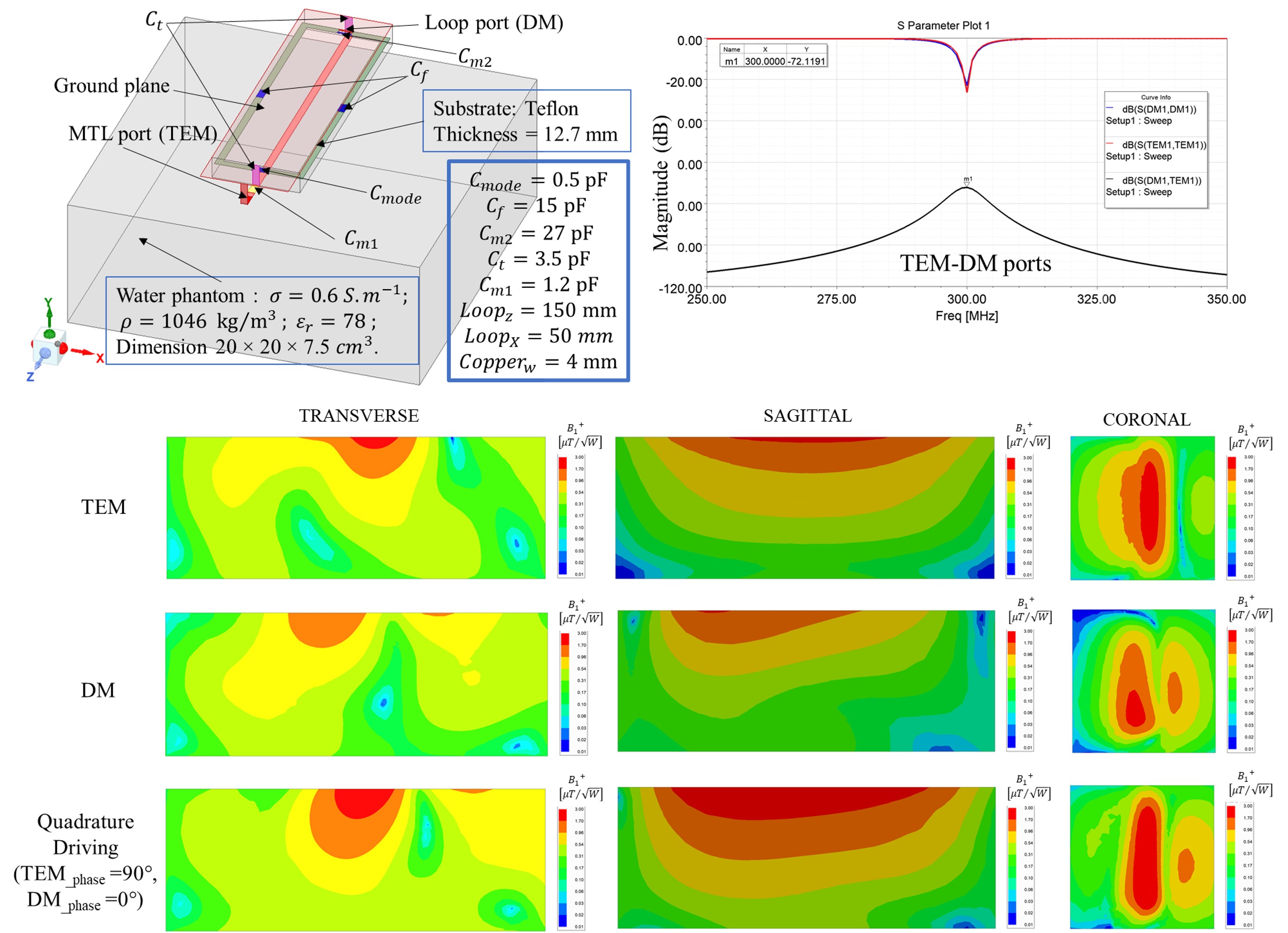
Fig. 1 Configuration of the hybrid (Loop + MTL) quadrature coil along with geometry dimension, electrical parameters and simulated scattering parameters. Simulated transmit $$$B_1^+$$$ field distribution normalized to 1 W of input power transversal, sagittal coronal plane for CM, DM and quadrature mode excitation.
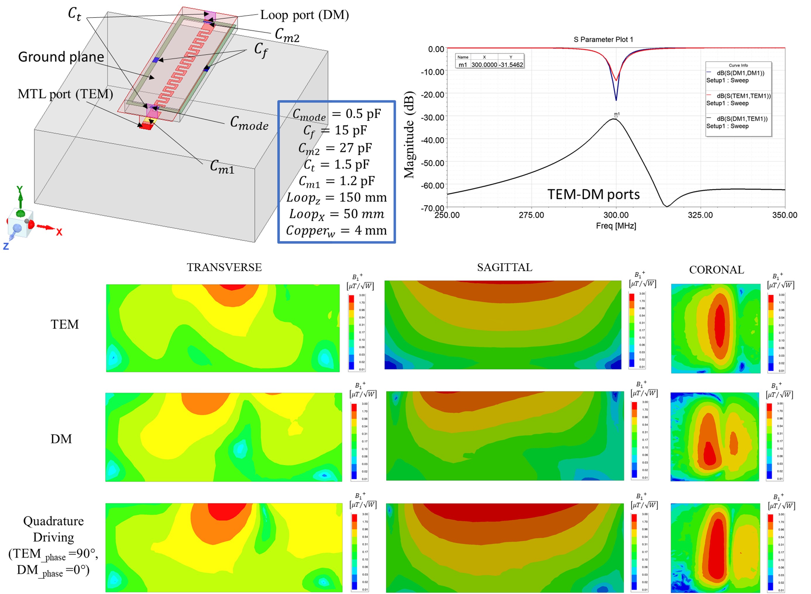
Fig.2 Configuration of the hybrid (Loop + meandered MTL) quadrature coil along with geometry dimension, electrical parameters and simulated scattering parameters. Simulated transmit $$$B_1^+$$$ field distribution normalized to 1 W of input power transversal, sagittal coronal plane for CM, DM and quadrature mode excitation.
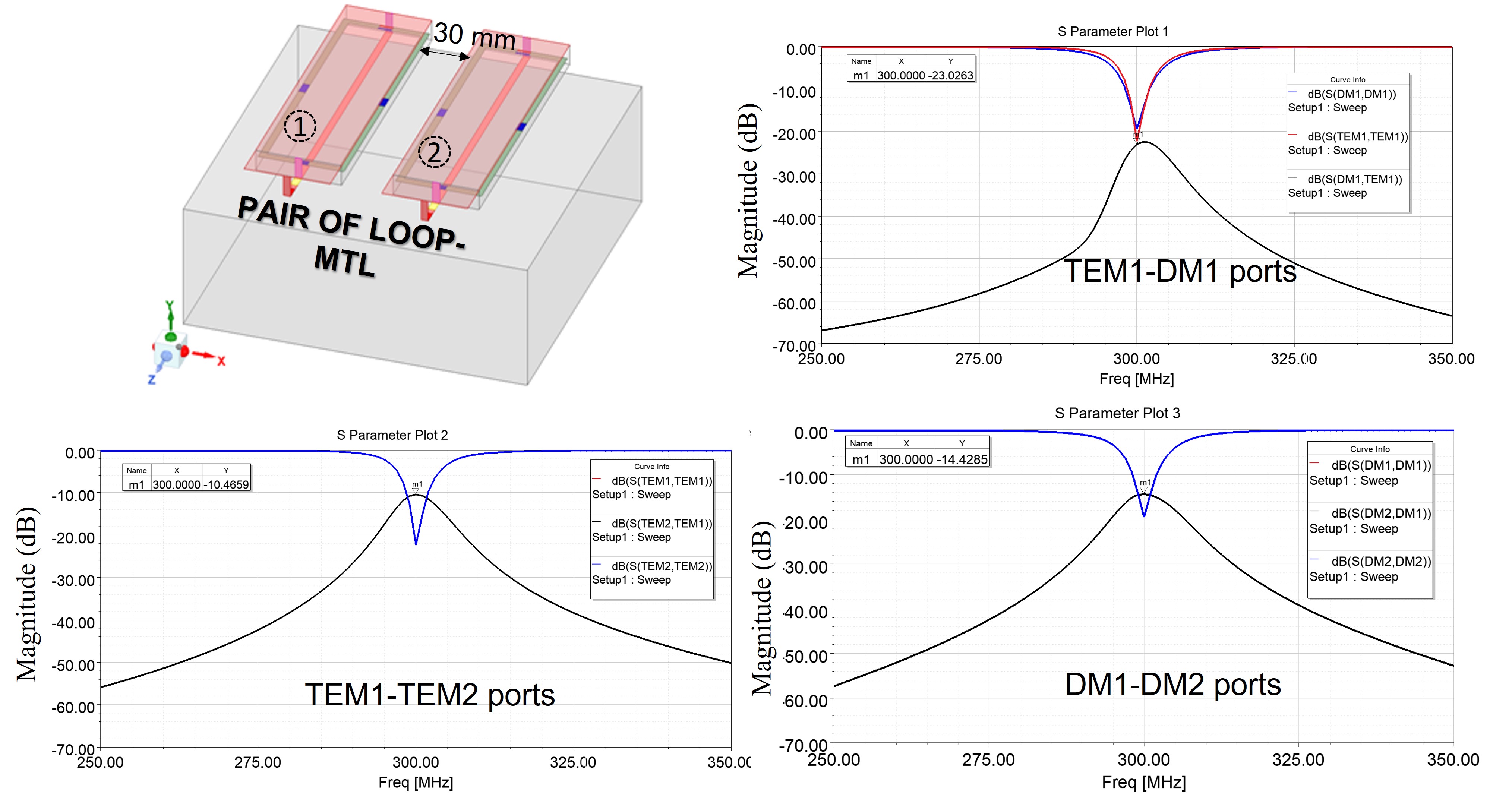
Fig.3 Pair of quadrature CMDM resonators on top of the phantom separated by 3 cm gap. Simulated frequency response this configuration showing the electromagnetic coupling between the multimode resonators.
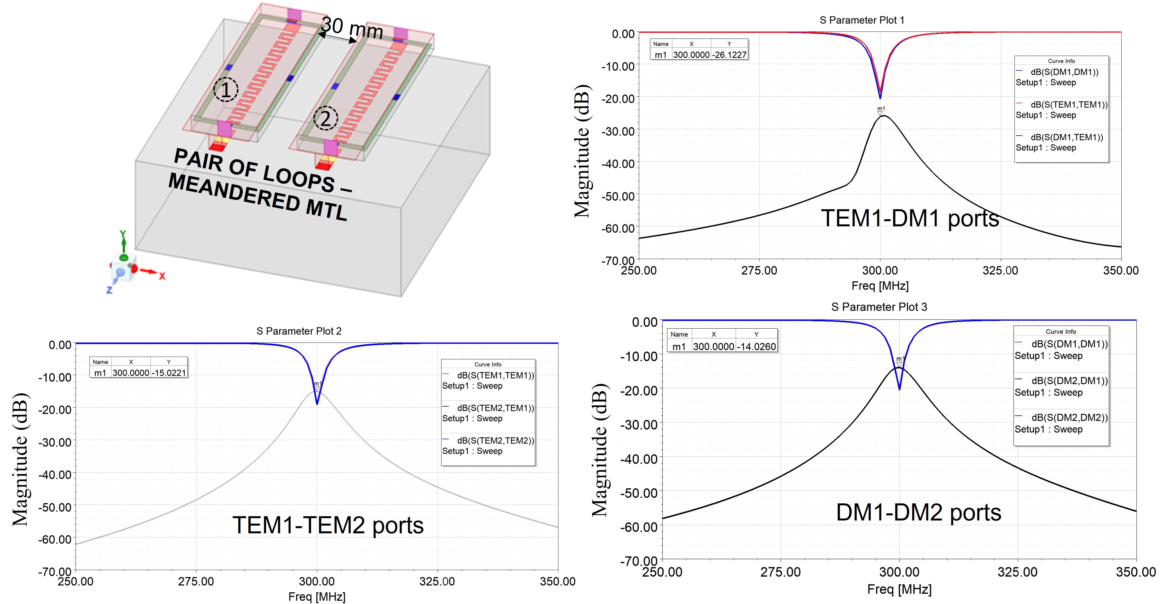
Fig.4 Pair of quadrature CMDM resonators with the magnetic wall decoupling on top of the phantom. Simulated frequency response this configuration showing the electromagnetic coupling between the multimode resonators.
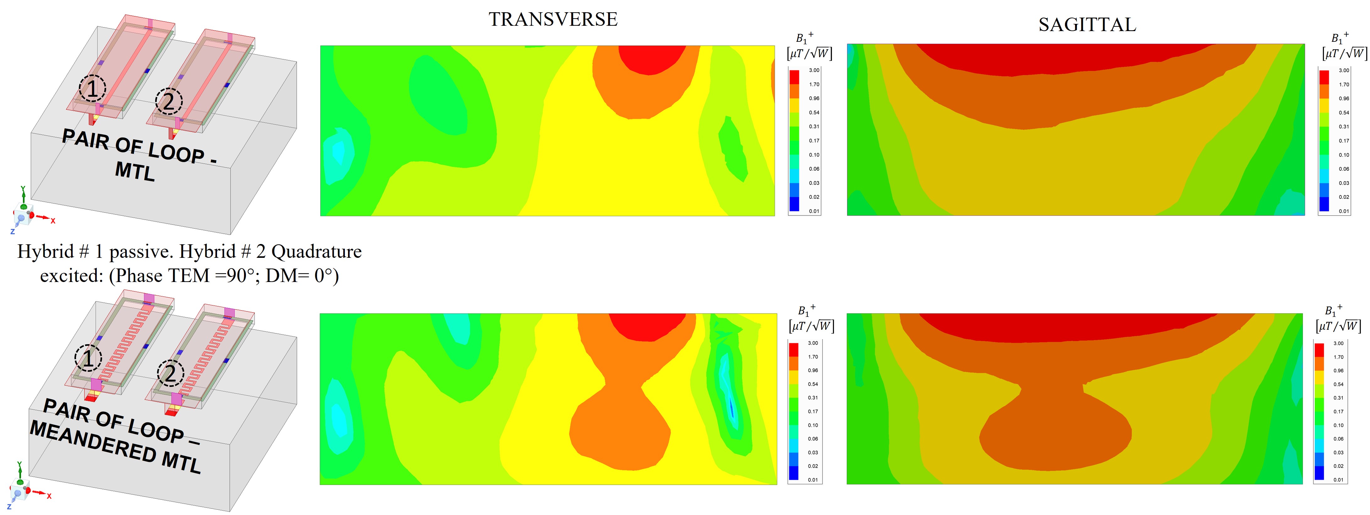
Fig.5 Simulated transmit $$$B_1^+$$$ field distribution normalized to 1 W of the accepted input power for 2-element array of both hybrid quadrature designs in the transversal and the longitudinal plane cutting through the center of the RF coils. The field map is illustrated within the phantom.
DOI: https://doi.org/10.58530/2022/4061