3948
Simulation of a shield effect on a J-pole antenna array for ultra-high field MR-PET1Institute of Neuroscience and Medicine - 4, Forschungszentrum Juelich, Juelich, Germany, 2RWTH Aachen University, Aachen, Germany, 3Institute of Neuroscience and Medicine - 11, Forschungszentrum Juelich, Juelich, Germany, 4JARA - BRAIN - Translational Medicine, Aachen, Germany, 5Department of Neurology, RWTH Aachen University, Aachen, Germany
Synopsis
Interest in simultaneously operating MR-PET systems as a means of accessing multiple biological parameters with high spatial and temporal resolution is increasing. In a hybrid acquisition, the RF antenna is used inside the PET FOV generating potential photon loss and artefacts. A multi-channel J-pole antenna array, which does not include any high-density parts in the imaging FOV, has been recently introduced, and its outstanding performance has been demonstrated. To prevent interference between MR and PET, including an RF shield is necessary. Here, we conducted a simulation to compare the characteristics of the J-shape antenna array with and without the shield.
Introduction
Simultaneously operating hybrid clinical systems are gaining in increasing interest inasmuch as they enable access to multiple biological parameters with the high spatial and temporal resolution, which can potentially provide synergetic diagnostic information.1 However, MRI and PET systems are not easily integrated, and any factors that may degrade the performance of either modality need to be avoided to ensure optimal quality across both modalities. In a hybrid MR-PET acquisition, the RF coil or antenna is generally positioned inside the PET imaging region and close to the subject, potentially resulting in attenuation and associated artefacts in PET. When the MR field strength increases, this problem is further exacerbated due to the reduced RF wavelength in tissue. In response to this issue, a new multi-channel J-pole (or J-shape) antenna array has been recently introduced, and its outstanding performance has been demonstrated.1,2 Interference between both modalities is another important factor to consider when integrating MRI and PET and is usually avoided with the use of a shield attached to the PET detector array and placed inside the MR magnet bore. However, as the shield is likely to be positioned in close proximity to the antenna array, it may have a compromising effect on its performance. In this study, we carried out a numerical electromagnetic simulation in order to anticipate the characteristics of the J-pole antenna array with the shield.Materials and methods
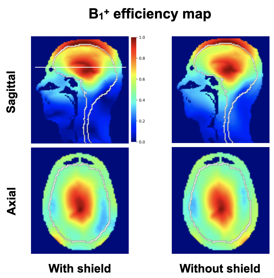
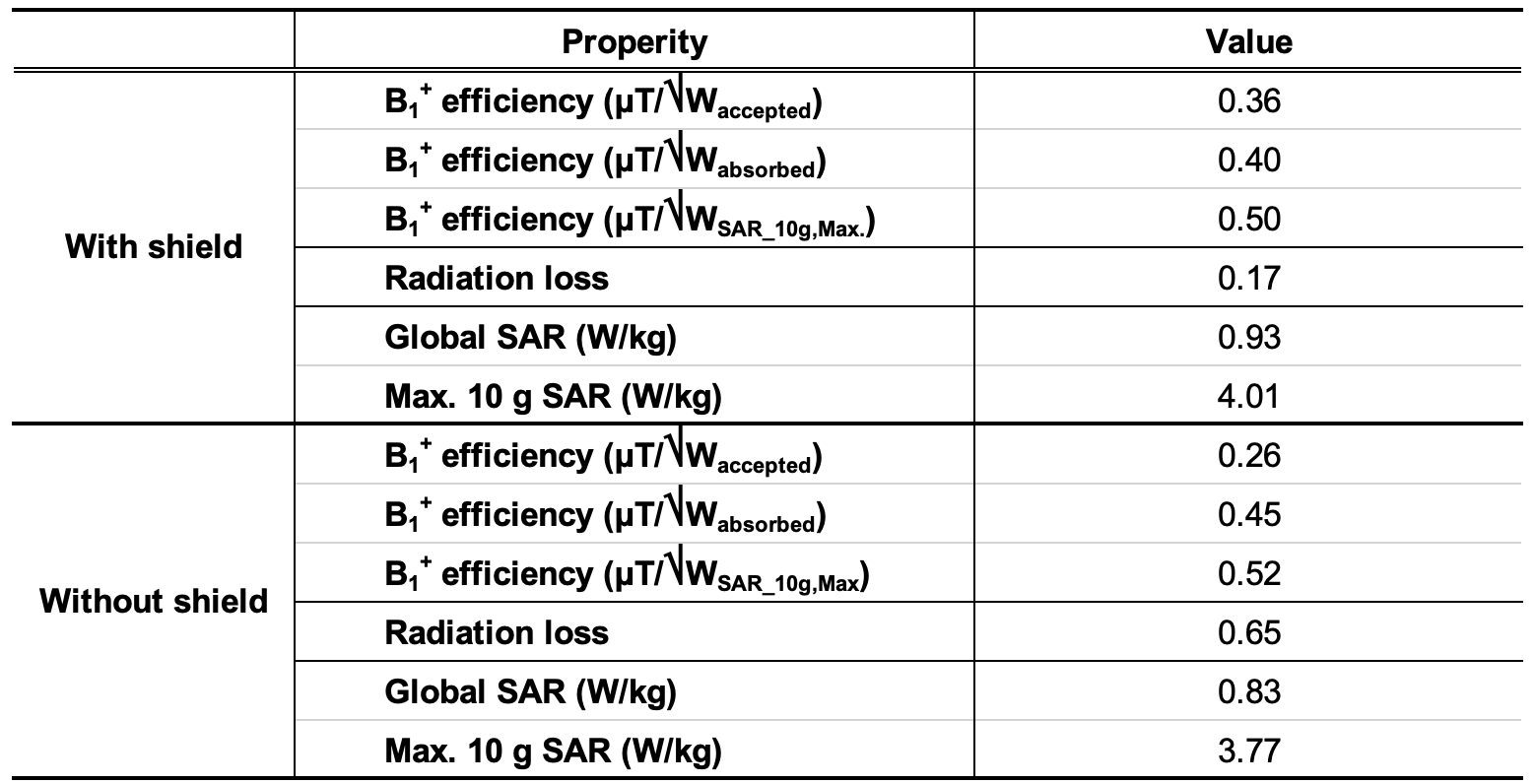
The CST Studio Suite (CST AG, Darmstadt, Germany) was utilised to conduct the finite integration technique simulations at 7 T. The J-pole antenna array was loaded with the head and part of the shoulders of the Duke voxel model (IT’IS-Foundation, Zurich, Switzerland).3 The J-pole antenna array was tuned at 7 T and matched to 50 Ω in the co-simulation. The PET shield was initially included in the simulation model, and the data were then compared to simulations without the shield. Fig. 1 shows the simulation model, including the J-pole antenna array, the Duke model and the shield. The dimensions of the shield are 360 mm in diameter and 634 mm in length. The dimensions were selected to be the same as our brain 7 T PET insert system currently under construction.4 The results of the transmit efficiency and SARglobal and SAR10g,Max generated by the J-pole array with/without the shield were analysed and compared. The average B1+ field strengths were calculated within the brain region. The transmit efficiencies with/without the shield were scaled to achieve the accepted power of 1W, absorbed power of 1W and SAR10g,Max of 1W.5,6Results
Fig. 2 shows simulated B1+ distributions of the Duke model in the sagittal (top) and the axial (bottom) imaging planes of the J-pole antenna array with (left columns) and without the PET shield (right columns). The straight white line in the sagittal image specifies the selected axial slice, and the white contour lines indicate the brain region. These parameters were used to calculate the average B1+ and SAR values, as shown in Fig. 3. Figure 3 also shows that the B1+ efficiency (SAR10g,Max) of the J-shape antenna array with/without shield is comparable, whereas improved efficiency is seen in the array with the shield when it is used with the accepted and absorbed power of 1W for normalisation. The figure further indicates that high radiation loss could result in efficiency loss. With the shield, the radiation loss appears to be significantly reduced, helping to improve the B1+ efficiencies, particularly when normalised using the accepted and absorbed power.7,8 The global and max. SAR values shown here were normalised to achieve the average transmit efficiency of 1 μT in the brain area.Discussion/Conclusions
Using a simulation tool, here we have investigated the potential effect of a PET shield on the newly developed, gamma-radiation-transparent MR antenna array at 7 T. The effect of the PET shield on the J-pole antenna array was not found to be significant and may actually help to reduce radiation loss. Moreover, it could potentially improve the performance of the antenna array at ultra-high field. In the future, we intend to further examine this J-pole antenna array on the scanner, together with the BrainPET insert, and to evaluate the sensitivity of the array by evaluating the signal-to-noise ratios.Acknowledgements
No acknowledgement found.References
1. Shah NJ, Hybrid MR-PET imaging: Systems, Methods and Applications, RSC, 2018.
2. Choi C-H, et al., Dipolantennen-array für hybride MR-PET und MR-SPECT Tomographen sowie dessen Verwendung und MR-PET oder MR-SPECT Tomograph mit einem Dipolantennen-Array, German patent application number 102019003949.1.
3. Choi C-H, et al., A novel antenna array for ultra-high field MR-PET, ISMRM 2021.
4. Christ A., et al., The virtual family – development of surface-based anatomical models of two adults and two children for dosimetric simulations, PMB, 2009.
5. Lerche CW, et al., Design and estimated performance of a UHF-MRI compatible BrainPET insert for neuroscience, IEEE NSS/MIC, 2020.
6. Shajan G, et al., Three-layered radio frequency coil arrangement for sodium MRI of the human brain at 9.4 tesla, MRM., 2016.
7. Hong S-M, et al., Design and evaluation of a 1H/31P double-resonant helmet coil for 3T MRI of the brain, PMB, 2019.
8. Wang B, et al., A radially interleaved sodium and proton coil array for brain MRI at 7 T, NMR in Biomed, 2021.9. Destruel A., et al., Integrated multi-modal antenna with coupled radiating structures (I-MARS) for 7T pTx body MRI, IEEE TMI, 2021.
Figures