3868
Wireless power transfer on non-main eigenmodes within birdcage coil1School of Physics and Engineering, ITMO university, Saint-Petersburg, Russian Federation
Synopsis
In this work, we investigate a concept of a wireless power transfer system for 1.5T MRI scanner. Our system exploits additional eigenmodes of a birdcage body coil that are not used during the scanning process. Such a solution could be implemented in existing hardware with a minor change in MRI components and at the same time minimize the interference between the power transfer system and imaging functions of the scanner.
Introduction
Wireless powering could be the next step in the evolution of MRI equipment. The external energy source permits the development of more lightweight coils and other in-bore devices without any cables1. This potentially leads to improvements in the patient comfort during a scan and shortening of the patient placement time. There are two main approaches to power up hardware inside the scanner bore wirelessly: wireless power transfer (WPT)1, 2, 3 and energy harvesting4, 5. WPT requires an additional transmit antenna, which complicates its application due to the need for auxiliary hardware and the occupation of valuable free space inside the tunnel. In turn, the energy harvesting approach may utilize existing components of the MRI machine so it’s more practically feasible. Usually, it takes part of the energy from the B1+ field created by the birdcage body coil at the Larmor frequency. Unfortunately, this also means that it has a great influence on the imaging process. To address both these issues, we propose to use a built-in birdcage body coil as a transmitting antenna for a WPT system but employ its non-main eigenmodes to prevent any interference at working frequency of the MRI scanner.Methods
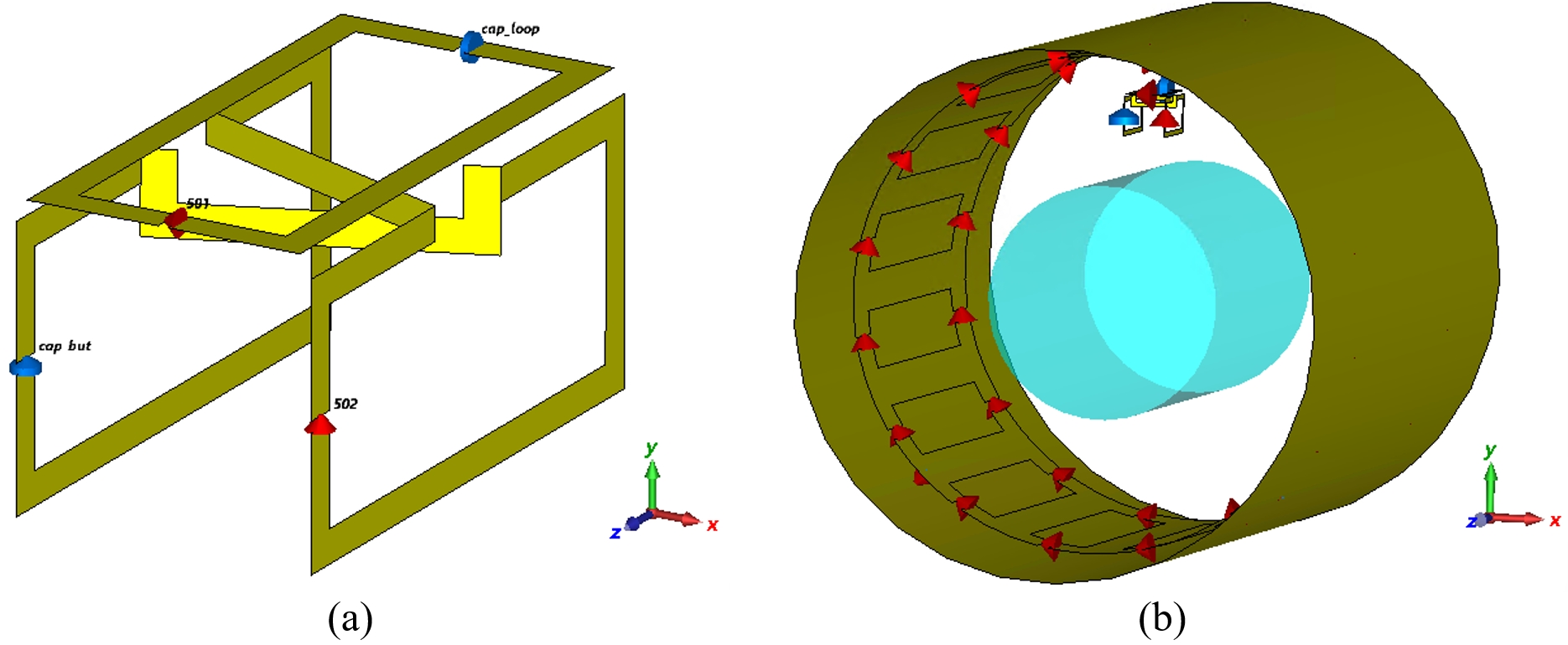
A classical birdcage coil is a multi-resonant structure that supports a set of eigenmodes. Only one of them called main is involved in the imaging process, while others are placed far from the MRI working range. A small circularly polarized antenna tuned to the corresponding eigenmode frequency can efficiently couple with the birdcage and receive some energy during the transmission of WPT signals. The structure of our dual channel antenna5 is shown in Fig.1 (a). Fig. 1 (b) demonstrates its position inside the realistic model of the high-pass body coil from the Siemens Avanto MRI scanner. Our simulation setup also includes a phantom with a diameter of 300 mm and a length of 500 mm filled with salted water (ε=80, σ=1S/m). All the simulations were performed by using CST Microwave Studio 2021 (Dassault Systèmes Simulia Corp., France) and frequency-domain solver. Circularly polarized B1+ fields were calculated for the next frequencies: 63.6 MHz (1.5T Larmor frequency, reference case), 53.2 MHz, 44.8 MHz, 39 MHz (non-main higher order eigenmodes). In each case receive antenna was properly tuned to establish efficient reception of the energy. Input power for the birdcage coil was set to 1 W per port. Both channels of the receive antenna were loaded with 2 Ohm resistors, emulating rectifiers inputs.Results
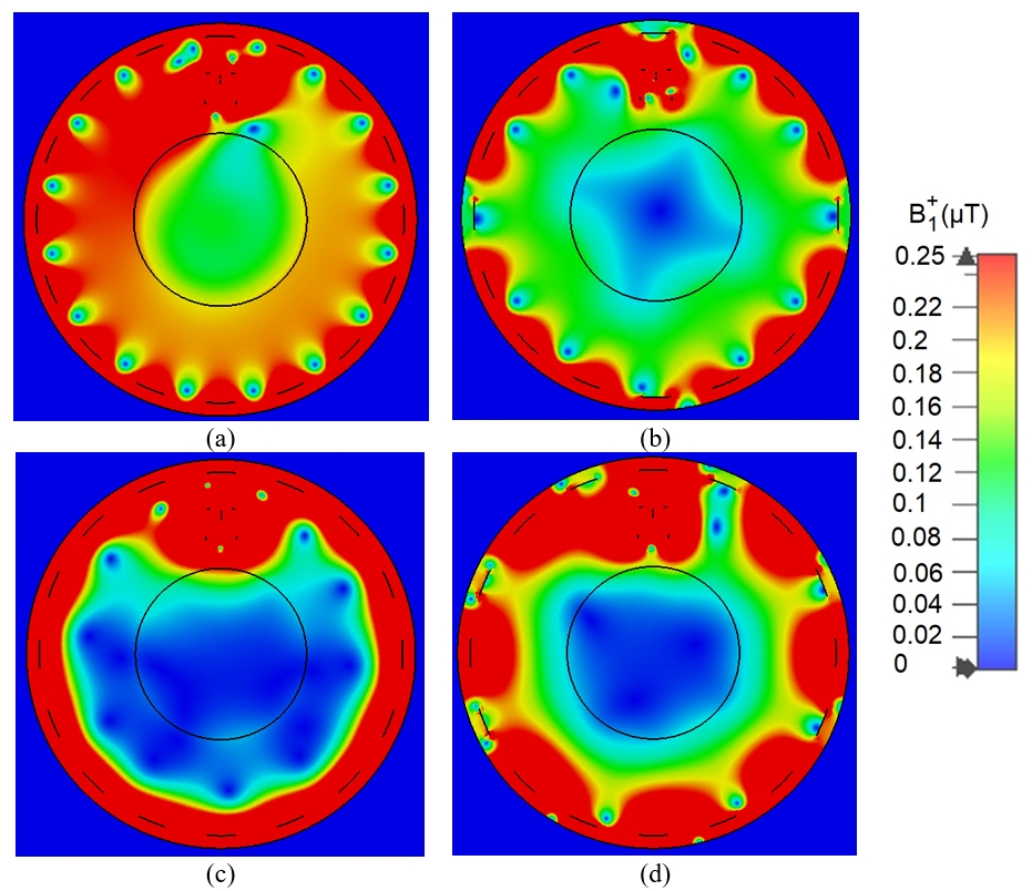
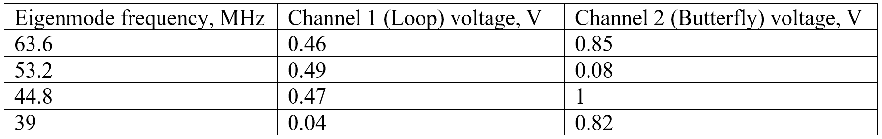
The simulation results with the B1+ fields are shown in Fig. 2. They clearly demonstrate why only the main eigenmode at frequency 63.6 MHz (Fig. 2(a)) is suitable for imaging purposes. All of the simulated non-main eigenmode fields (Fig. 2(b-d)) are concentrated closer to the surface of the birdcage coil and far from the object of interest. But this is not a problem for the WPT system, because its antenna must be located exactly in such regions. The case in Fig. 2 (a) actually is a harvesting setup. It demonstrates an issue with the field distortions created by the presence of a small resonant antenna that causes artifacts on images. This case was used as a reference in our efficiency comparison. We used the simulated voltages across the loads as measures. These values are shown in Figure 3. It should be noticed that each eigenmode has its unique spatial field configurations that result in different voltage values for two orthogonal channels of the receive antenna. Surprisingly, some of the eigenmodes (39 MHz and 53.2 MHz) reveal themself as linearly polarized so they could not be used for our dual channel WPT.Discussion and Conclusion
Eigenmode in Fig. 1 (c) with the frequency 44.8 MHz shows the best results in all considered cases so it is suitable for the WPT system. It also allows using the full capabilities of circular polarization in energy transfer, providing the best coupling with the birdcage coil. Furthermore, we assume that such lower frequency and remote location of regions with increased field strength could positively influence the specific absorption rate (SAR). This is especially important if we want to preserve acceptable safety levels for the patients performing MRI procedures.Acknowledgements
This work was supported by the Russian Science Foundation (Project No.21-79-30038).References
1. L. Nohava, J. C. Ginefri, G. Willoquet, E. Laistler, & R. Frass-Kriegl, Perspectives in wireless radio frequency coil development for magnetic resonance imaging. Frontiers in Physics, 8, 11 (2020)
2. K. Byron, F. Robb, S. Vasanawala, J. Pauly, & G. Scott, A wireless power transfer system for mri scanners. In 2018 IEEE Wireless Power Transfer Conference (WPTC) (pp. 1-4). IEEE (2018, June)
3. A. Ganti, J. Lin, T. Wynn, & T. Ortiz. Achieving electromagnetic compatibility of wireless power transfer antennas inside MRI system. Wireless Power Transfer, 6(2), 138-153 (2019)
4. M. Venkateswaran, K. Kurpad, J. E. Brown, S. Fain, & D. van der Weide, Wireless Power Harvesting During MRI. In 2020, 42nd Annual International Conference of the IEEE Engineering in Medicine & Biology Society (EMBC) (pp. 1469-1472). IEEE (2020, July)
5. Pavel S. Seregin, Georgy A. Solomakha, Egor I. Kretov, Oleg I. Burmistrov and Alexey P. Slobozhanyuk, Circularly polarized coil for 1.5 T MRI RF harvesting, Proc. Intl. Soc. Mag. Reson. Med., No.29, pp. 1587 (2021)
Figures