3866
Miniaturized and Reproducible Phase Shifters using Capacitor-Loaded Transmission Lines for Add-On RF Shimming at High Field
Ming Lu1, Yue Zhu2,3, John Gore2,3,4, William A. Grissom2,3,4, and Xinqiang Yan2,3
1College of nuclear equipment and nuclear engineering, Yantai University, Yantai, China, 2Vanderbilt University Institute of Imaging Science, Vanderbilt University Medical Center, Nashville, TN, United States, 3Department of Radiology and Radiological Sciences, Vanderbilt University Medical Center, Nashville, TN, United States, 4Department of Biomedical Engineering, Vanderbilt University, Nashville, TN, United States
1College of nuclear equipment and nuclear engineering, Yantai University, Yantai, China, 2Vanderbilt University Institute of Imaging Science, Vanderbilt University Medical Center, Nashville, TN, United States, 3Department of Radiology and Radiological Sciences, Vanderbilt University Medical Center, Nashville, TN, United States, 4Department of Biomedical Engineering, Vanderbilt University, Nashville, TN, United States
Synopsis
Add-on RF shimming devices, including phase shifters, could provide additional degrees of freedom for RF transmit chains to improve field uniformity and reduce SAR. At the Larmor frequencies of MRI, however, the transmission line length for realizing large phase shifts becomes unrealistically long. We introduce a capacitor-loaded transmission line design to build a miniaturized microstrip line phase shifter for RF shimming at high fields. The fabricated phase shift boards had a miniaturized size of 3 x 4 cm2, exhibited a low loss of < 0.26 dB, and cost much less than those made from other materials.
Introduction:
Add-on RF shimming devices, including phase shifters, power splitters, and/or power combiners [1–9], could provide additional degrees of freedom for RF transmit chains to improve field uniformity and reduce SAR. Phase shifters can be made from lumped-element circuits or coaxial cables, but are laborious to design and construct when a large number of shifters with high phase accuracy are required. An alternative approach is to use printed transmission lines. At MRILarmor frequencies, however, the transmission line lengths for large phase shifts become unrealistically long. For instance, a 360-degree transmission line at 300 MHz (Larmor frequency of 7T) is ~60 cm long using FR4 substrate. To reduce the sizes of transmission lines and make them suitable for massive splitting networks, we developed a shorter, capacitor-loaded transmission line.Methods:
This work was inspired by Hirota et al [10] who showed how a quarter-wavelength transmission line could be shortened by adding capacitors at the ends, while increasing the characteristic impedance. To suit MRI RF shimming applications, we first extended this concept to arbitrary angles. For a transmission line with a characteristic impedance of Z0 and an electric angle of θ0 (Figure 1a), its admittance (Y-) matrix may be expressed as Ya (Figure 2). When loaded with capacitors (C) at both ends, the Y-matrix of a shorter transmission line with a characteristic impedance of θ (Figure 1b) may be Yb (Figure 2). Comparing Ya and Yb, the shorter line could achieve the same Y-matrix as the standard transmission line ifθ = arccos (cosθ0 + ωCZ0sinθ0) [1]
and Z = Z0sinθ0/sinθ [2]
Figure 3a depicts the trace layouts of capacitor-loaded transmission lines in EM simulations (Ansys HFSS). The relative phase shift increased from 0 to 180 degrees in steps of 15 degrees at 298 MHz. The capacitors were chosen to have commercially available values such as 3.3 pF or 4.7 pF [11]. The trace widths and initial trace lengths were calculated from Eqs. 1 and 2. Then the trace widths were kept to fixed values while the lengths were finely adjusted to achieve the expected phase shift and minimize return loss. For transmission lines with electric angles > 90 degrees, two capacitor-loaded lines in series were used (Figure 1c). The Dissipation Factor and dielectric constant (Dk) of the 1.2-mm-thick substrate were set to 0.011 and 4.6, to mimic the properties of an economical FR4 board (Shengyi S1000H).
Based on the simulation results, a set of boards were manufactured (Figure 3b) and tested with a 2-port VNA (Copper Mountain TR1300/1). These boards have a miniaturized size of 3 x 4 cm2 and are suitable for massive splitting networks. Terminated capacitors were picked from 5% tolerance fixed non-magnetic capacitor pools (PPI) with an Agilent LCR meter.
Results:
Figure 4 compares the expected, simulated, and measured phase shifts of different capacitor-loaded transmission lines. The average phase error of simulation and fabrication boards is 0.3 and 2.6 degrees, respectively. The measured results on real boards agree well with the calculations and simulations considering inevitable board fabrication and component tolerances.Figure 5a plots the simulated and measured impedance matching of these boards, while Figure 5b plots the simulated and measured insertion losses. The simulated insertion losses were between 0.01 and 0.23 dB, while the measured insertion losses were between 0.01 and 0.26 dB. The insertion loss of the large-phase-shift circuit was substantially lower than that of a standard transmit line (0.26 dB vs. ~0.5 dB, for 180-degree-shift).
Discussions:
Capacitor-loaded transmission lines are well suited for MRI for two reasons. First, non-magnetic capacitors widely used in MRI have many fewer parasitic parameters compared to inductors, and their values can be measured accurately with widely available instruments. Second, although this design has the downside of reduced bandwidth, it is not problematic for MRI applications as the required bandwidth is extremely narrow (< 1 MHz). In Zhu et al [12], the authors demonstrated that the power splitting ratio in HP-RAPS circuits could be adjusted by varying the microstrip’s phase shift. Therefore, this miniaturized phase shifter design could be used for manipulating both the magnitude and phase weights in RF shimming. Although the trace length/board size could be reduced by using high-Dk materials (such as Rogers 3010) [4], the size-reduction is limited and these substrates have much higher cost (two orders of magnitude).Conclusion:
We introduce a capacitor-loaded transmission line design to build a miniaturized microstrip line phase shifter for RF shimming at high fields. The design has been analyzed by theory and validated by full-wave electromagnetic simulation and bench tests. The fabricated phase shift boards have a miniaturized size of 3 x 4 cm2, exhibit a low loss of < 0.26 dB, and cost much less than those made from other materials. All board designs will be made open source and can be easily reproduced.Acknowledgements
This work was in part supported by NIH R01 EB016695 and R21 EB029639.References
- G. Adriany et al., “Transmit and receive transmission line arrays for 7 Tesla parallel imaging,” Magnetic Resonance in Medicine, vol. 53, no. 2, pp. 434–445, 2005, doi: 10.1002/mrm.20321.
- V. Alagappan et al., “Degenerate mode band-pass birdcage coil for accelerated parallel excitation,” Magnetic Resonance in Medicine, vol. 57, no. 6, pp. 1148–1158, 2007, doi: 10.1002/mrm.21247.
- G. J. Metzger, C. Snyder, C. Akgun, T. Vaughan, K. Ugurbil, and P.-F. Van de Moortele, “Local B1+ shimming for prostate imaging with transceiver arrays at 7T based on subject-dependent transmit phase measurements,” Magnetic Resonance in Medicine, vol. 59, no. 2, pp. 396–409, 2008, doi: 10.1002/mrm.21476.
- P. Yazdanbakhsh and K. Solbach, “Microstrip Butler matrix design and realization for 7 T MRI,” Magnetic Resonance in Medicine, vol. 66, no. 1, pp. 270–280, 2011, doi: 10.1002/mrm.22777.
- P. Yazdanbakhsh, K. Solbach, and A. K. Bitz, “Variable Power Combiner for RF Mode Shimming in 7-T MR Imaging,” IEEE Transactions on Biomedical Engineering, vol. 59, no. 9, pp. 2549–2557, Sep. 2012, doi: 10.1109/TBME.2012.2205926.
- Z. Cao, X. Yan, and W. A. Grissom, “Array-compressed parallel transmit pulse design,” Magnetic Resonance in Medicine, vol. 76, no. 4, pp. 1158–1169, 2016, doi: 10.1002/mrm.26020.
- X. Yan, Z. Cao, and W. A. Grissom, “Experimental implementation of array-compressed parallel transmission at 7 tesla,” Magnetic Resonance in Medicine, vol. 75, no. 6, pp. 2545–2552, 2016, doi: 10.1002/mrm.26239.
- X. Yan, Z. Cao, and W. A. Grissom, “Ratio-adjustable power splitters for array-compressed parallel transmission,” Magnetic Resonance in Medicine, vol. 79, no. 4, pp. 2422–2431, 2018, doi: 10.1002/mrm.26847.
- C. Sun et al., “A retrofit to enable dynamic steering for transmit arrays without multiple amplifiers,” Magnetic Resonance in Medicine, vol. 85, no. 6, pp. 3497–3509, 2021, doi: 10.1002/mrm.28632.
- T. Hirota, A. Minakawa, and M. Muraguchi, “Reduced-size branch-line and rat-race hybrids for uniplanar MMIC’s,” IEEE Transactions on Microwave Theory and Techniques, vol. 38, no. 3, pp. 270–275, Mar. 1990, doi: 10.1109/22.45344.
- “Ultra-low ESR Capacitors | RF Capacitors | Microwave Components.” https://www.passiveplus.com/ (accessed Nov. 02, 2021).
- Y. Zhu, M. Lu, W. A. Grissom, J. C. Gore, and X. Yan, “Hybrid-pair ratio adjustable power splitters for add-on RF shimming and array-compressed parallel transmission,” Magnetic Resonance in Medicine, vol. n/a, no. n/a, doi: 10.1002/mrm.28934.
Figures
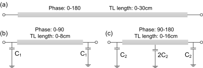
Figure 1.
(a) Conventional transmission line. (b) and (c) Capacitor-loaded transmission
lines. For transmission lines of > 90-degree shift, two capacitor-loaded
lines in series were used. The capacitor-loaded design could highly reduce the
trace length and thereby board size. In this work, the trace length was reduced
by 50%.
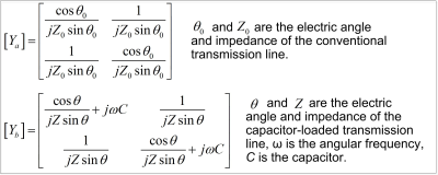
Figure 2. Admittance (Y-) matrices of a standard
transmission line (Ya) and a capacitor-loaded transmission line (Yb).
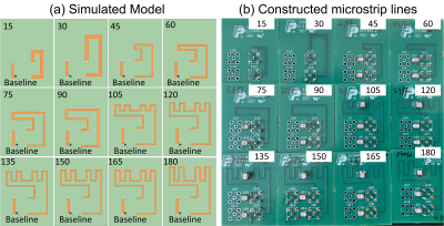
Figure
3. (a) Simulated model (b) photographs of capacitor-loaded transmission line
phase shifters with different phases.
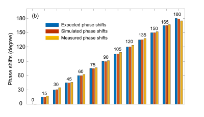
Figure
4. Expected, simulated, and measured phase shifts of different capacitor-loaded
transmission lines.
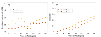
Figure
5. Simulated and measured insertion loss (a) and impedance matching (b)
performance. For all phase shifts, the simulated and measured impedances well
matched to 50 Ω, with S11<-20 dB. The simulated and measured
insertion loss with phase shift of 180 degree is ~0.25 dB, which is 50% less
than that of a standard long transmission line.
DOI: https://doi.org/10.58530/2022/3866