3759
Automatic Targeting of the Dorsolateral Subthalamic Nucleus for Functional Connectivity Guided rTMS Therapy1Center for Cognition and Brain Disorders, The Affiliated Hospital of Hangzhou Normal University, Hangzhou, China, Hangzhou, China, 2Institute of Psychological Sciences, Hangzhou Normal University, Hangzhou, China, Hangzhou, China, 3Zhejiang Key Laboratory for Research in Assessment of Cognitive Impairments, Hangzhou, China, Hangzhou, China, 4Centre for Cognitive and Brain Sciences, University of Macau, Macao SAR, China, Taipa, Macau, 5Unit of Psychiatry, Department of Public Health and Medicinal Administration, & Institute of Translational Medicine, Faculty of Health Sciences, University of Macau, Macao SAR, China, Taipa, Macau, 6Faculty of Health Sciences, University of Macau, Macao SAR, China, Taipa, Macau, 7Department of Neurosurgery, Beijing Tiantan Hospital, Capital Medical, Beijing, China, 8MR Research, GE Healthcare, Shanghai, China, Shanghai, China, 9Institute of sports medicine and health, Chengdu Sport University, Chengdu, China, Chengdu, China
Synopsis
The current study developed an AutoSTN method to help automatically localize the dorsolateral STN (DL-STN) according to steps in deep brain stimulation (DBS). Furthermore, for the consideration of the RS-fMRI FC-guided rTMS clinical study and application, we developed one-stop plug-in named ‘CC-CAT’ which could serve any RS-fMRI FC-guided rTMS treatment.
INTRODUCTION
It has been recently proposed that the repetitive transcranial magnetic stimulation (rTMS) on the superficial cortex target would take treatment effect via resting-state functional magnetic resonance imaging (RS-fMRI) functional connectivity (FC) with a deep region 1,2. The dorsolateral subthalamic nucleus (DL-STN), the key component in both direct and indirect motor circuit as well as one of deep effective targets in deep brain stimulation (DBS) surgery for the treatment of Parkinson’s disease (PD). However, the DL-STN targeting highly depend on well-trained neurosurgeons and does not suitable for FC-guided rTMS. Therefore, the current study aimed to; 1) develop a method for automatically localizing the DL-STN based on its RS-fMRI FC analysis; 2) develop a one-stop plug-in FC analytic toolbox for assisting future individualized FC guided-rTMS.METHODS
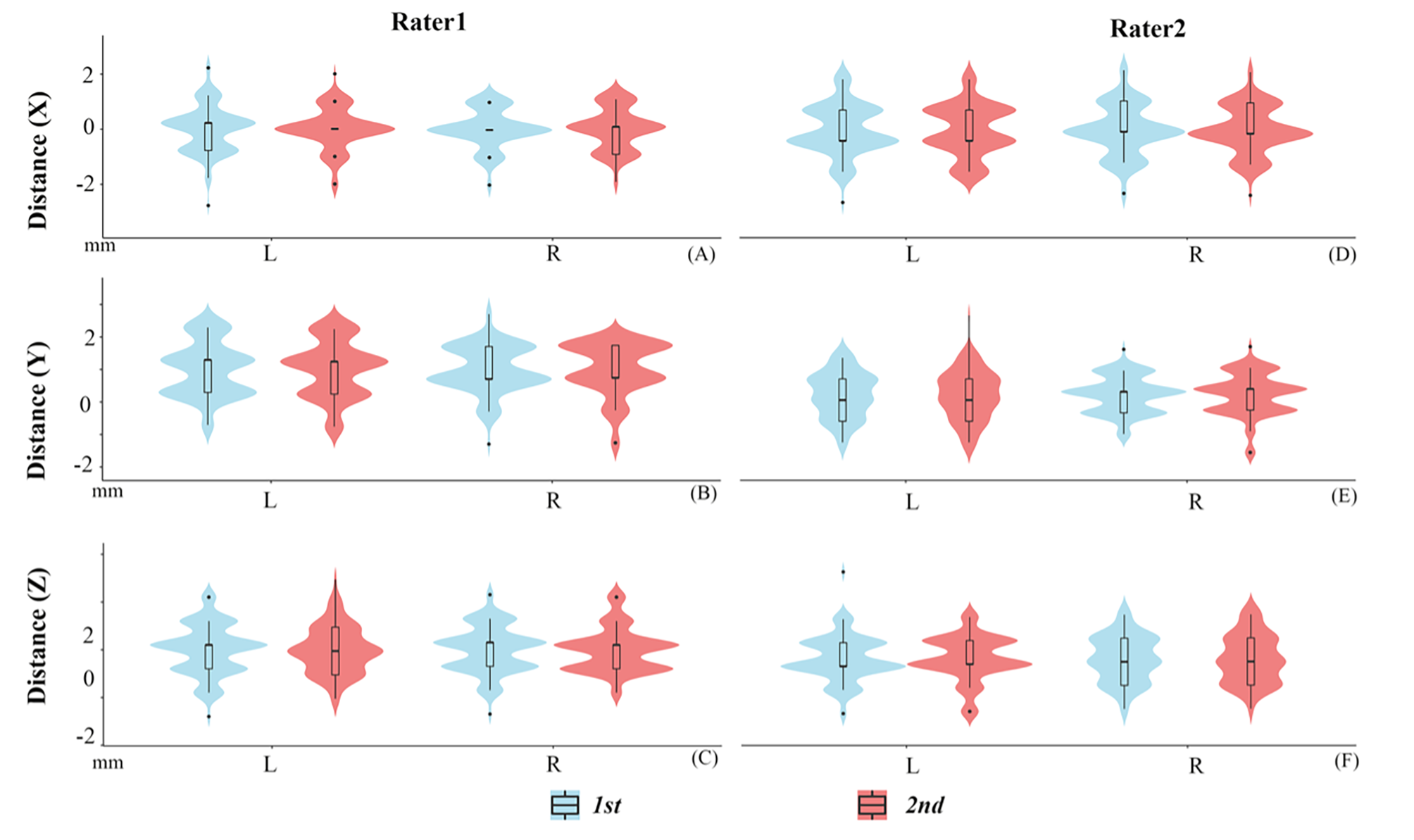
Seventy-eight healthy subjects were scanned with RS-fMRI, 3D-enhanced susceptibility weighted angiography (ESWAN), and 3D-T1 image. We first manually reoriented T1 image to AC-PC stereotactic space. Then, ESWAN image was coregistered to the T1 image in AC-PC stereotactic space. After that, the DL-STN coordinates were localized by two independent raters (ZN, YJ), and each rater targeted it twice (1st, 2nd) based on the coregistered ESWAN image as Figure 1 according to the steps of defining DL-STN in DBS surgery 3,4. The intra-rater and inter-rater distances of x, y, and z coordinates for each subject were calculated using intra-class correlation (ICC). Moreover, the distances of x, y, and z directions between the individual and the average DL-STN coordinates were also calculated. As the distances between the individual and the averaged coordinates were less than 2 mm (x, y, and z coordinates) for 93.6% subjects and within a voxel, we defined the average coordinates (the left DL-STN, x = -11.89 ± 0.82; y = -14.51 ± 1.00; z = -6.40 ± 1.01; the right DL-STN, x = 12.53 ± 0.77; y = -13.97 ± 0.86; z = -6.57 ± 0.99.) as “AutoSTN” coordinates, help the automatically target the DL-STN. Further, the AutoSTN coordinates were defined as the seed for each subject and then performed FC. For assisting future FC-guided rTMS treatment, we developed a one-stop plug-in FC analytic toolbox named ‘Connectivity and Coordinates Converting Assistant Toolbox (CC-CAT)’ based on RESTplus (http://restfmri.net/forum/). CC-CAT needs only the NIFTI data and the seed-FC coordinates in MNI space. Researchers can select the peak FC coordinates in a superficial cortex as the rTMS target.RESULTS
1) Both DL-STN coordinates displayed high intra- and inter-rater reliability with ICC higher than 0.95 for all conditions (different groups, definitions and raters).2) The differences of the x, y, and z axes between the individual and the average coordinates were less than 2 mm for 93.6% subjects within a voxel. Five (6.4%) subjects’ coordinates indicated 2-3 mm distant from the average DL-STN coordinates (Figure 2). The averaged DL-STN coordinates, i.e., AutoSTN coordinates, were as follows: DL-STN on the left, x: -11.89 ± 0.82; y: -14.51 ± 1.00; z: -6.40 ± 1.01; DL-STN on the right, x: 12.53 ± 0.77; y: -13.97 ± 0.86; z: -6.57 ± 0.99.
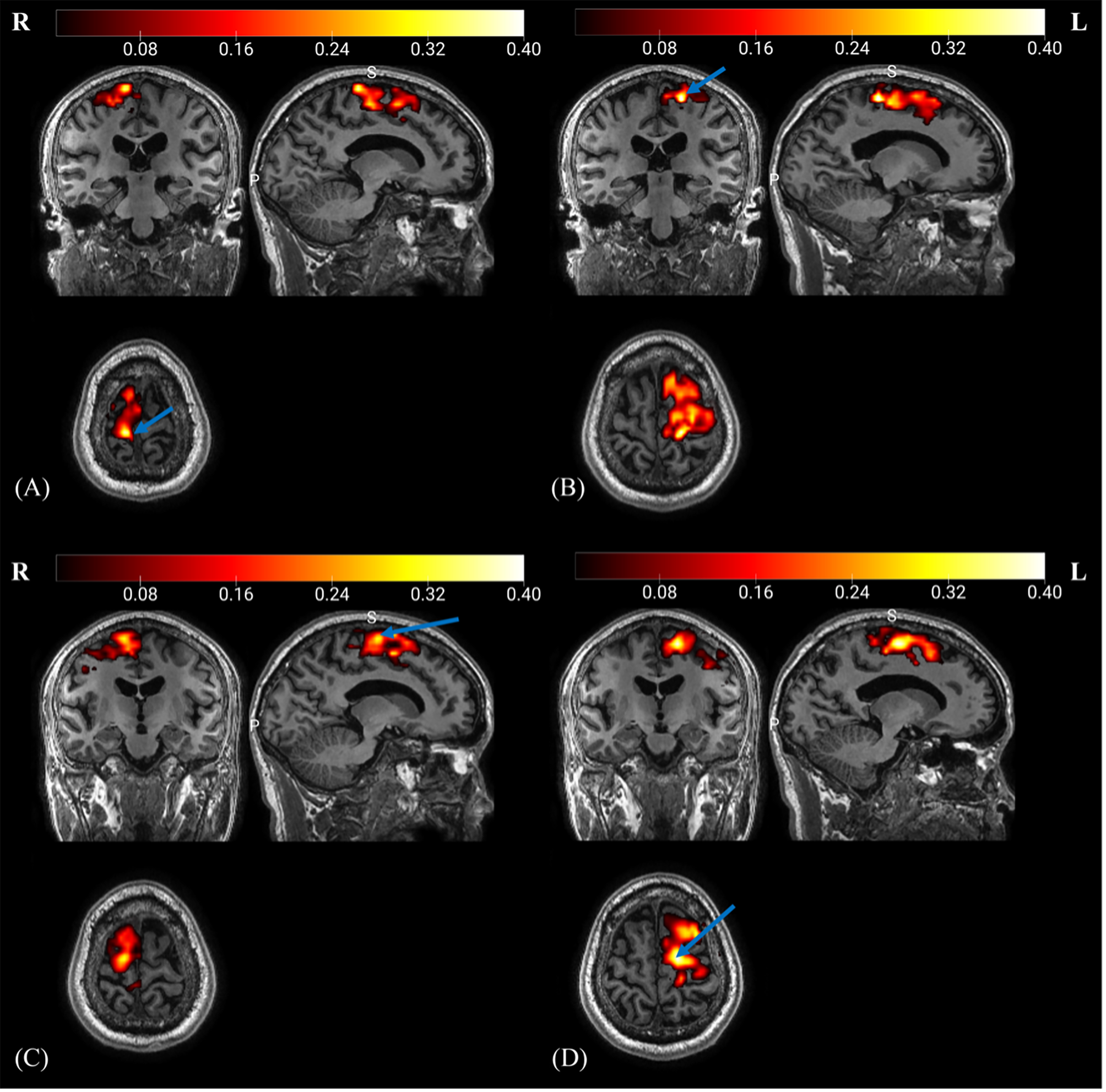
3) The DL-STN displayed significant FC with motor cortices both at group and individual level which is validated by the new developed ‘CC-CAT’ plug-in (Figure 3).
DISCUSSION
Although image-based DL-STN targeting in DBS surgery has been well established with modern MRI techniques, e.g., ESWAN, it is a challenge to manually localize multiple anatomical landmarks. Here, we provided an AutoSTN method to automatically localize DL-STN coordinates. The AutoSTN method was performed based on the image-based DL-STN targeting method by manually localizing the DL-STN targets of 78 healthy subjects to obtain the average coordinates. It has been shown that the image-based DL-STN targeting method displayed the smallest variance compared with the indirect targeting method based only on AC and PC landmarks or the image-only direct targeting method, which was closely associated with the optimal electrode contact with satisfactory clinical outcome 3,4.Our study revealed that only 5 (6.4%) subjects displayed distances in the x, y, and z directions between the individual and the averaged DL-STN coordinates higher than 2 mm but less than 3 mm, implying that the average DL-STN coordinates can be used as the coordinates for most people, which allowed for the development of AutoSTN coordinates.
In addition, based on the software RESTplus, a one-stop plug-in toolkit named ‘CC-CAT’ for automatic seed-based FC analysis was developed. As shown in our FC analysis results (Figure 3), future rTMS studies could consider the peak FC coordinates in the motor cortices as stimulation targets for rTMS therapy. We validated the one-stop plug-in and obtained the same results as those of DPABI (http://www.rfmri.org/dpabi) (Figure 3). Moreover, the CC-CAT supports any seed-based FC in both individual original space and standard space. Researchers could select the peak FC coordinates in the original space as the rTMS stimulation target.
CONCLUSION
The AutoSTN could help automatically localize the DL-STN coordinates. Further, one-stop plug-in named ‘CC-CAT’ can serve the future any FC-guided rTMS therapy.Acknowledgements
None.References
1. Fox MD, Buckner RL, White MP, Greicius MD, Pascual-Leone A. Efficacy of transcranial magnetic stimulation targets for depression is related to intrinsic functional connectivity with the subgenual cingulate. Biol Psychiatry. 2012;72(7):595-603.
2. Cash RFH, Zalesky A, Thomson RH, Tian Y, Cocchi L, Fitzgerald PB. Subgenual Functional Connectivity Predicts Antidepressant Treatment Response to Transcranial Magnetic Stimulation: Independent Validation and Evaluation of Personalization. Biol Psychiatry. 2019;86(2):e5-e7.
3. Andrade-Souza YM, Schwalb JM, Hamani C, et al. Comparison of three methods of targeting the subthalamic nucleus for chronic stimulation in Parkinson's disease. Neurosurgery. 2008;62 Suppl 2:875-883.
4. Lozano CS, Ranjan M, Boutet A, et al. Imaging alone versus microelectrode recording-guided targeting of the STN in patients with Parkinson's disease. Journal of neurosurgery. 2018:1-6.
Figures