3696
Fabrication and evaluation of bilateral Helmholtz radiofrequency coil for thermo-stable breast image with reduced artifacts1Department of Radiology, Research Institute of Radiological Science, Severance Hospital, Yonsei University College of Medicine, Seoul, Korea, Republic of, 2Department of Radiology, Washington University School of Medicine, St. Louis, MO, United States, 3Department of Nuclear Medicine, Severance Hospital, Yonsei University College of Medicine, Seoul, Korea, Republic of, 4Department of Radiology, Stanford University School of Medicine, Stanford, CA, United States, 5Department of Biomedical Engineering, and Research Institute of Biomedical Engineering, College of Medicine, The Catholic University of Korea, Seoul, Korea, Republic of
Synopsis
The positron emission tomography (PET)-magnetic resonance (MR) system is a newly emerging technique that yields hybrid images with high-resolution anatomical and metabolic information. With PET-MR imaging, a definitive diagnosis of breast abnormalities will be possible with high spatial accuracy and images will be acquired for the optimal fusion of anatomic locations. Therefore, we propose a PET-compatible 2-channel breast MR coil with minimal disturbance to image acquisition which can be used for simultaneous PET-MR imaging in patients with breast cancer.
Introduction
The positron emission tomography (PET)-magnetic resonance (MR) hybrid images can be potentially used for various diagnostic purposes in oncology, cardiology, and neurology with a real-time recording of morphologic, physiologic, functional, and metabolic study1,2. The metallic components of the breast coil with numerous leads and solders disturb photon transmission and image acquisition during the PET scan despite attenuation correction (AC)3. The aims of this study were to modify the conventional breast coil for a PET-MR scanner, to minimize interference to data acquisition during the PET scan, and to improve image quality based on computed tomography (CT) images with a comparable signal-to-noise ratio (SNR) during the MR examination, in comparison with PET-CT images obtained with the conventional breast MR coil.Materials and Methods
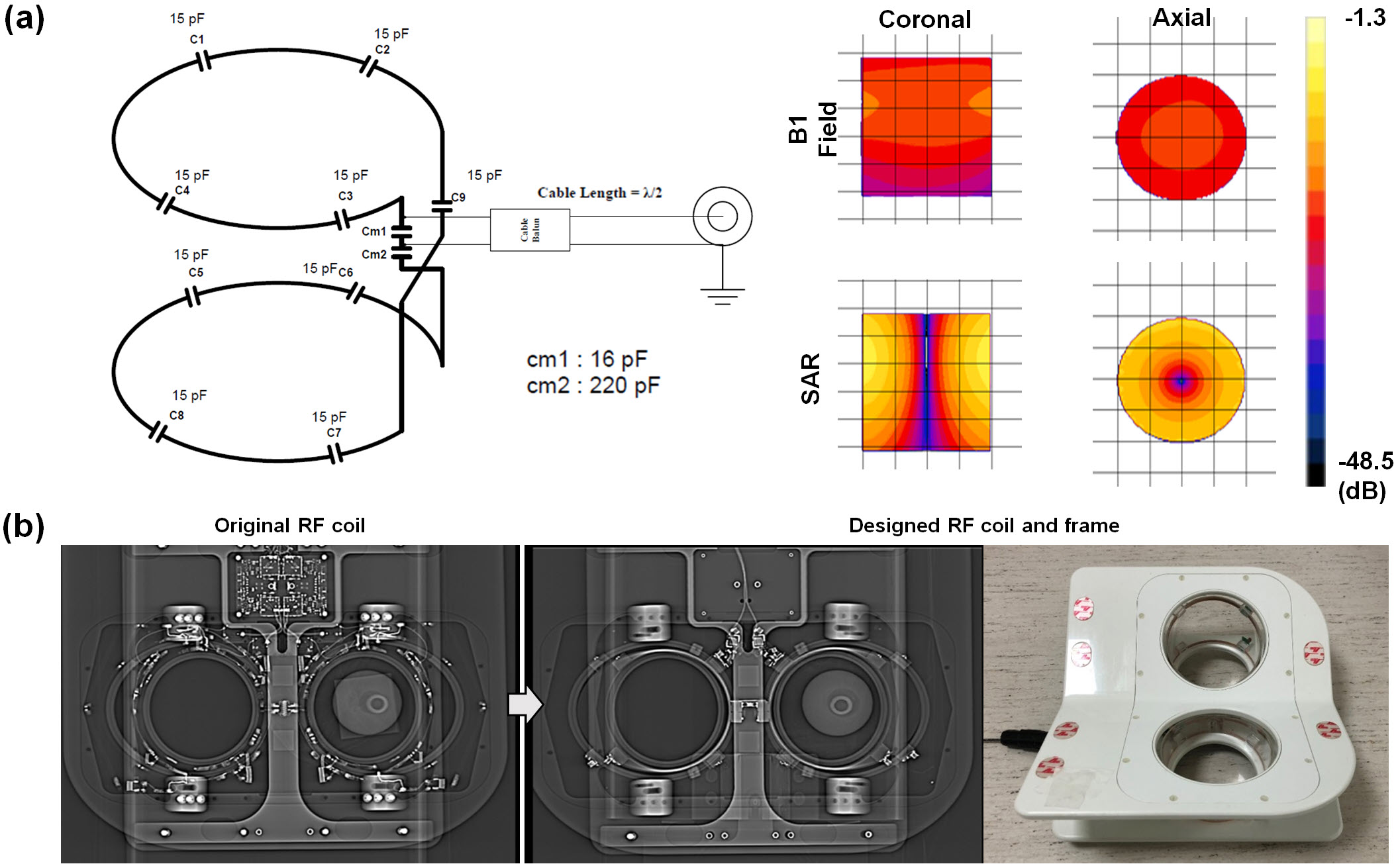
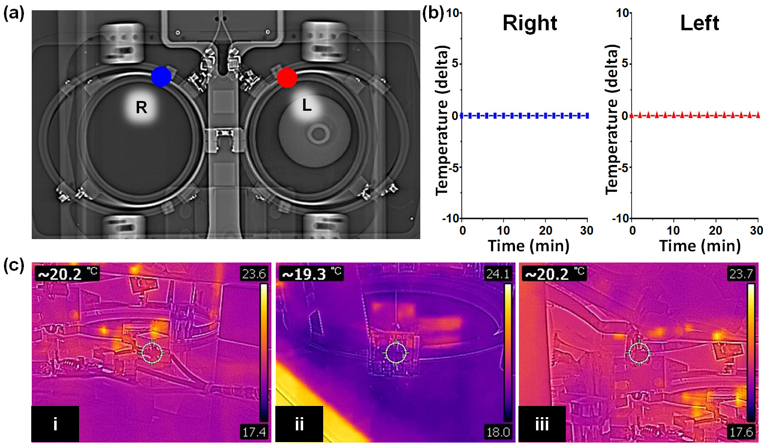
For electromagnetic simulation, a SEMCAD X (Ver. 14.2.1) as a 3D full-wave electromagnetic and thermal simulation platform based on the Finite-Difference Time-Domain and Finite Element Method was employed to design the coil geometry and numerical loading phantom. The intrinsic B1 field distribution in the numerical phantom with a cylindrical shape full of body fluid with relative permittivity (εr = 69.062), electric conductivity (σ = 1.5053 S/m), and loss tangent (tanδ =3.0851) was investigated. All of the metal screws in the frame were replaced with plastic screws and ceramic capacitors, previously embedded coils were removed, and the remaining metallic components in the local field of view (FOV) area were removed and rearranged in an area out of the local FOV on comparison radiographs (Figure 1). For MR scanning, the coil was connected to a coil interface box (3.0 Tesla 1H gateway). The LNA had a 25 dB gain, 0.4 dBm noise figure, and 1 ± 0.5Ω input impedance. The decoupling/coupling driver voltages (-5V/3V) derived from the coil interface box supplied the coils separately. The PET-CT scans were obtained on a Discovery 600 PET-CT (GE Healthcare). 18F-FDG (0.5 mCi) was mixed with normal saline in a plastic bottle which was used as a phantom to evaluate image artifacts. CT and PET images of the phantom with FDG were obtained with each coil for comparison. CT scans were performed prior to obtaining PET images with the following parameters: voltage current, 120 kVp, and 60 mA; exposure time, 5074 ms; data collection diameter, 500 mm; distance source to detector, 949.075 mm; distance source to object, 541 mm; standard body filter; slice thickness, 3.75 mm; helical mode; spiral pitch factor, 0.9375; single collimation width, 1.25; total collimation width, 20; and CT dose index vol, 2.41 mGy. These CT images were converted to a 511 keV photon attenuation map and used for PET attenuation correction. PET images were reconstructed using a standard Ordered Subset Expectation Maximization 3D-iterative algorithm with n iterations and nn subsets. All MR scans were performed on a 3.0 Tesla clinical scanner (GE Healthcare). Clinical breast MR images for the volunteer scan were acquired using the following scan parameters: (1) T1-weighted image with spectral fat suppression; TR, 694 ms; TE, 9.6 ms; echo train length (ETL), 4; slice thickness, 3 mm; slice gap, 0 mm; matrix size, 320 × 256; and scan time, 3min 39s; (2) T2-weighted image; TR, 9592ms; TE, 102ms; matrix size, 416 × 256; ETL, 20; and scan time, 4min 21s. To evaluate safety with respect to temperature, temperature changes occurring during scanning were directly monitored throughout the MR examination for a maximum of 33 minutes simultaneously using an MR-compatible optic temperature probe within the coil (Figure 2).Results
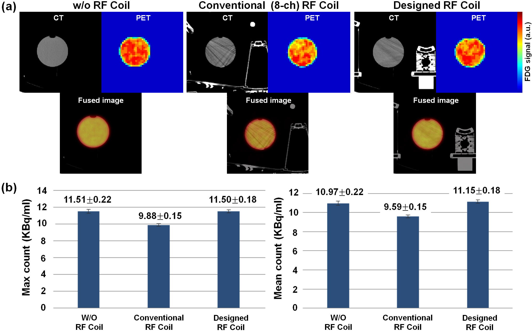
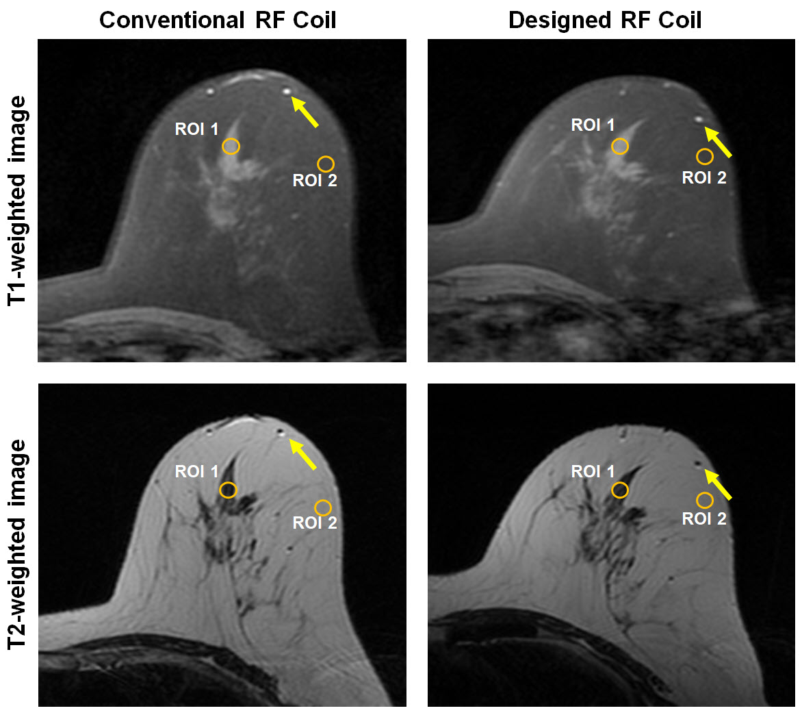
Regarding image quality during the PET-CT scan, which used the same window setting as the CT scan, we were able to see more streak signs that suggested beam hardening with conventional coil compared with the designed coil, especially in the plastic bottle (Figure 3). The average hounsfield unit (HU) ± standard deviation in the center region of interest (ROI) was 0.41 ± 3.72 HU for the center slice of the phantom with w/o coil, -4.51 ± 13.54 HU with the designed coil, and 2.38 ± 29.36 HU with the standard conventional coil. The max count of the conventional coil was low (9.88 ± 0.15). The max count of the designed coil (11.50 ± 0.18) was similar to that of the w/o coil (11.51 ± 0.22). The conventional coil showed a high standard deviation (10.97 ± 0.65), which corresponded to the heterogeneous photon density count map. Figure 4 shows clearly delineated fine morphological features such as a 2-mm-wide blood vessel and parenchymal contour. The differences in SNR between the conventional and the designed coil was 175.2 vs. 207.7 in ROIs of parenchymal and fat tissue regions.Discussion and Conclusion
In this study, we developed a preliminary RF coil design with Helmholtz loops of transmit-receiver coils for breast MR images that can be used in a PET-MR system. PET and MR image experiments using various phantoms showed that the proposed RF coil could provide comparable image quality for SNR and HU and result in fewer artifacts on the PET scan than the standard dedicated breast MR coil. These preliminary findings warrant further investigation and future modifications of our design will help develop a less metallic breast MR coil that is suitable for use in an MR-PET hybrid system.Acknowledgements
This study was supported by the Research Institute of Radiological Science, Yonsei University College of Medicine and by the Basic Science Research Program of the National Research Foundation of Korea funded by the Ministry of Science, ICT& Future Planning, Republic of Korea (Grant 2013R1A1A3013165 & 2017R1A2B4010407).References
1. Rauscher I, Eiber M, Fürst S, et al. PET/MR imaging in the detection and characterization of pulmonary lesions: technical and diagnostic evaluation in comparison to PET/CT. J Nucl Med. 2014;55(5);724-729.
2. Neuner I, Kaffanke JB, Langen KJ, et al. Multimodal imaging utilising integrated MR-PET for human brain tumour assessment. Eur Radiol. 2012;22(12);2568-2580.
3. Oehmigen M, Lindemann ME, Lanz T, Kinner S, Quick HH. Integrated PET/MR breast cancer imaging: Attenuation correction and implementation of a 16‐channel RF coil. Med Phys. 2016;43(8Part1);4808-4820.
Figures