3585
A Parallel-Transmit Halbach Magnet TRASE MRI System1Oncology, University of Alberta, Edmonton, AB, Canada
Synopsis
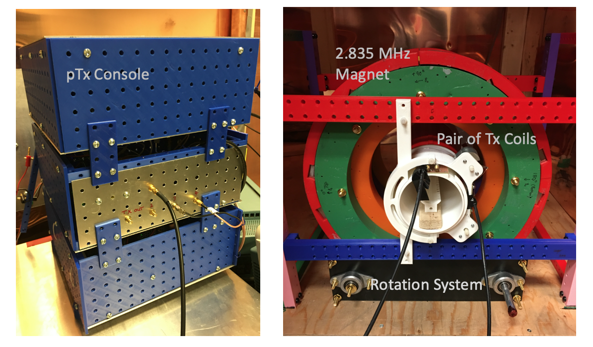
We have designed and constructed a low-field TRASE RF imaging system. In TRASE k-space encoding is achieved by refocusing with RF phase gradients. The system includes a motorized rotatable magnet, twin RF power amplifiers, two geometric decoupled truncated twisted solenoid RF transmit coils (1D radial TRASE encoding), and a multi-channel transmit SDR console. The magnet is a 2.835 MHz 8-ring Halbach design. All components are custom made. An inherent axial gradient of the inhomogeneous magnet function as slice selection. The unique feature of this imaging configuration is the simplicity. Two RF channels and magnet rotation provide multi-slice projection reconstruction imaging.
Introduction
TRASE (Transmit Array Spatial Encoding) achieves k-space encoding without B0 field gradient coils (1). The 1D TRASE sequence consists of an echo train in which each echo represents a different k-space location. Refocusing pulses are applied alternately on two RF phase gradient coils. TRASE is suited for low-cost, low-field magnet use. We have previously demonstrated 1D and 2D TRASE encoding at 8-9MHz in a homogeneous magnet. In this work we apply TRASE in the more accessible low field 2-3MHz and lower homogeneity regime. Towards the aim to minimize system cost, we use 1D TRASE encoding only and employ rotation to collect a full set of projections.Methods
Magnet: A 25 kg sparse dipolar Halbach magnet was built for TRASE MRI purposes (2), with short length and small size (< 43 cm x 43 cm x 25 cm). The positions of 320 N40UH magnetic pieces (1’’ x 1’’ x 1/2’’) was optimized using a genetic algorithm and constructed using 3D printed formers. The constructed 66.7 mT magnet is an accurate representation of the optimized design with a measured homogeneity of 11,152 ppm in a 12.7 cm diameter, 1 cm long cylindrical ROI. The magnet has an inherent axial gradient for z-dimensional encoding but improvements are being made. (A. Purchase, submitted).Magnet Rotation: To rotate the Halbach magnet, we used a hybrid stepper motor and a 2-phase hybrid stepper servo driver (NEMA24 motor, HSS60 driver, Changzhou RATTM MOTOR CO., Ltd, China). Control is from 5V pins, Arduino MEGA 2560. Angular precision: 0.04 deg.
RFPA: TRASE requires a high duty cycle, multi-channel RF amplifier system. The custom-built, dual-channel RF amplifier is capable of 1 kW peak RF power per channel at 50% duty cycle (however ~10W used in these experiments). In addition, the amplifier has a broad operating frequency range (1.5 – 50 MHz). The short delay times (15 us) between the gate and RF as well as a low blanking noise level comparable to commercial RF amplifiers allows high-resolution in-vivo TRASE (3).
RF Coils: Coils are based on the geometrically decoupled nested twisted solenoid design (3,4).
Two RF coil sets were built: a solenoid + saddle configuration and a pair of truncated twisted solenoids (suitable for rotation experiments). In each case coils are geometrically decoupled (i.e. no PIN diodes). In both cases, coil diameters were 100mm and 125mm with length 230mm. Imaging volume 80mm diam; 100mm length. Peak RF power for 200us pulses ~10W. Phase gradient strengths: 5.8deg/cm inner; 5.15 deg/cm outer coil. Further details of coil design will be given elsewhere (C. Sedlock, submitted).
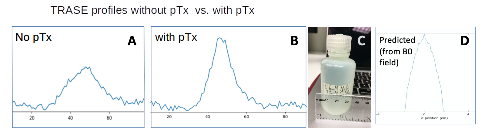
NMR Console: A new parallel transmit console (‘DNMR’) was designed and built for this project. The console is based around an AD9106 4-channel 12-bit DAC and waveform generator ADC chip (180 MSPS, 24-bit tuning word), and an ADC-SoC FPGA-CPU board (Terasic). This system fulfils the requirement of the TRASE sequence of parallel transmit with hard pulses, with well-defined amplitude, frequency and phase. The parallel transmit capability allows the cancellation of residual coil coupling (9).
Operation: At each magnet angle, a series of T1 interleaved multi-slice 1D TRASE echo trains are acquired. Magnet inhomogeneity acts as a slice gradient. Between each projection angle only small increments are required (~ 1 deg), which can be achieved sub-second. The three encoding dimensions are radial TRASE encoding; multi-frequency; and rotation angle.
Results
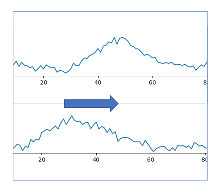
The parallel transmit capability cancels induced currents from residual coil coupling, resulting in improved TRASE encoding (9), Figure 2. Clean TRASE 1D profiles (200us pulses; 128 echoes) were obtained at a series of magnet rotation angles (0…90deg), corresponding to a full 2D k-space coverage (Fig.3). This preliminary set of projections verifies that TRASE can be used in inhomogeneous B0 fields. Implementation of 2D multislice image reconstruction is under development. Expected spatial resolution ~ 1-2mm range.Discussion
An advantage of this system is that magnet inhomogeneity acts as a slice selection gradient, so RF pulse bandwidth requirement is much lower than other approaches in which inhomogeneity acts as a readout gradient. Short hard pulses may be used and frequency sweep is not required. The ideal magnetic field inhomogeneity is a linear axial gradient of the order of 10 mT/m, however other field patterns are useable with suitable reconstruction techniques. Magnet shimming to this end is currently being investigated. Geometric coil decoupling, enhanced with pTx, allows for effective TRASE spatial encoding.This eliminates diode switching (avoiding switching delays and glitches) and so allows rapid pulsing (corresponding directly to high spatial resolution).This also lowers system complexity and should scale well to larger coil dimensions. Data from the 1D TRASE sequence is simple to process and more resistant to artifacts than more complex 2D sequences (1), due to the very regular repeating pattern of pulses in the echo train.Conclusions
A new robust configuration for low-field 2D multislice MRI has been presented. The minimal requirement is a rotatable inhomogeneous low-field magnet with axial gradient; two RF transmit channels; two twisted solenoids Tx coils, moderately well geometrically decoupled (~ S12 -15 dB). An alternative configuration with 1 or 2 additional Tx channels would avoid the need for rotation, at the cost of additional system complexity.Acknowledgements
No acknowledgement found.References
1. J. C. Sharp, S.B. King, MRI using radiofrequency magnetic field phase gradients, Magn. Reson. in Med. 63 (2010) 151–161. doi:10.1002/mrm.22188.
2. A. R. Purchase et al., "A Short and Light, Sparse Dipolar Halbach Magnet for MRI," in IEEE Access, vol. 9, pp. 95294-95303, 2021
3. A.R. Purchase· T.Pałasz H.Sun J.C. Sharp, B. Tomanek. A high duty‑cycle, multi‑channel, power amplifier for high‑resolution radiofrequency encoded MRI. Magnetic Resonance Materials in Physics, Biology and Medicine (2019) 32:679–692
4. Sun H, Yong S, Sharp JC. The twisted solenoid RF phase gradient transmit coil for TRASE imaging. J Magn Reson. 2019; 299:135–150.
5. Sun H, AlZubaidi A, Purchase A, Sharp JC. A geometrically decoupled, twisted solenoid single-axis gradient coil set for TRASE. Magn Reson Med 2019; 83:1484–98.
6. Sun, H. Ph.D. Thesis 2021, Radio-frequency Transmit Coils and Imaging Techniques for TRASE MRI, University of Alberta.
7. C. Zimmerman Cooley, J.P. Stockmann, B.D. Armstrong, M. Sarracanie, M.H. Lev, M.S. Rosen, L. L. Wald. Two-dimensional imaging in a lightweight portable MRI scanner without gradient coils. Magn Reson Med 73:872–883, (2015)
8. G. E. Sarty, L. Vidarsson. Magnetic resonance imaging with RF encoding on curved natural slices. Magn. Reson.Imag. 46 (2018) 47-55
9. P.Bohidar, H.Sun, J.C. Sharp, G.E. Sarty. The effects of coupled B1 fields in B1 encoded TRASE MRI - A simulation study. MRI 74 2020 74-83
Figures