3584
Shimming a Halbach Magnet for TRASE MRI on the International Space Station1Oncology, University of Alberta, Edmonton, AB, Canada, 2Biomedical Engineering, University of Saskatchewan, Saskatoon, SK, Canada
Synopsis
Astronauts experience detrimental loss to bone and muscle during long-term space flight. MRI is desired to monitor bone and muscle loss, but current portable systems remain unsuitable for the International Space Station (ISS). We built a 25 kg dipolar Halbach magnet dedicated to the transmit array spatial encoding (TRASE) method over a cylindrical region of interest (ROI), which satisfies the requirements for MRI on the ISS. Still, the natural axial gradient is not well suited to slice selection because it has a quadratic-type profile producing unwanted aliasing. We propose a technique to implement a linear axial B0 gradient for encoding.
Introduction
Bone and muscle loss experienced by humans in microgravity remains a significant concern for space flight and future space exploration1,2. Monitoring of these harmful effects in astronauts consists of extensive medical examinations before and after space flight due to limited medical devices on the International Space Station (ISS)1.MRI is a highly desired diagnostic technology due to its exceptional soft-tissue contrast imaging of human pathologies3,4. However, MRI systems remain unavailable on the ISS, partly due to their high weight and large size, associated with standard MRI systems5.
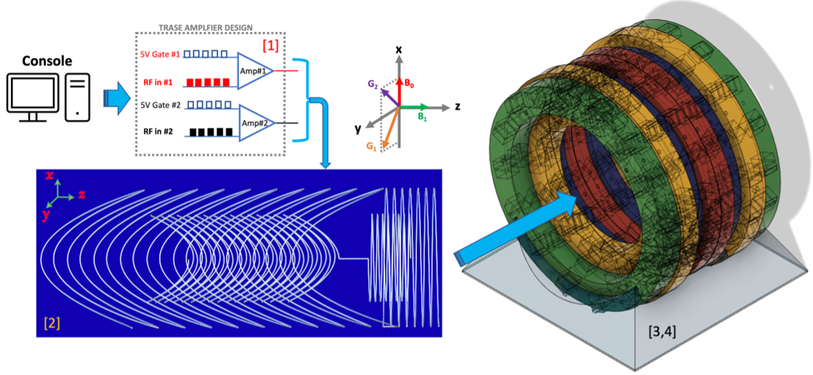
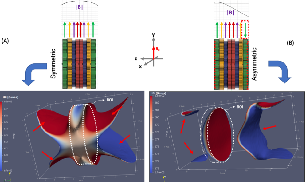
Recently, our group constructed a short and light Halbach magnet fulfilling the requirements and safety risks identified by the Canadian Space Agency (CSA) for an MRI suitable for the ISS6,7. The designed magnet is ideal for the transmit array spatial encoding (TRASE) technique which allows imaging without switched B0 gradients and weakens the main magnet homogeneity requirement, reducing MRI system weight, size, complexity and costs6. The twisted-solenoid RF coils for TRASE are capable of high-resolution encoding in a 2D plane (Figure 1)8,9,10. Since the magnetic field inhomogeneity acts as a slice selection, the natural B0 gradient is not well suited for encoding due to the non-linear quadratic profile of the field (Figure 2A)6.
Several groups have improved the field homogeneity or the built-in gradient linearity in a Halbach magnet by optimizing the blocks' size and magnetization orientations at fixed locations11,12,13. This work aimed to shape the B0 field in an existing Halbach magnet to a linear axial B0 gradient using an array of small permanent magnets. For example, an array of magnets in the asymmetric configuration provides an axial B0 gradient enabling 2D TRASE encoding (Figure 2B)7.
Methods
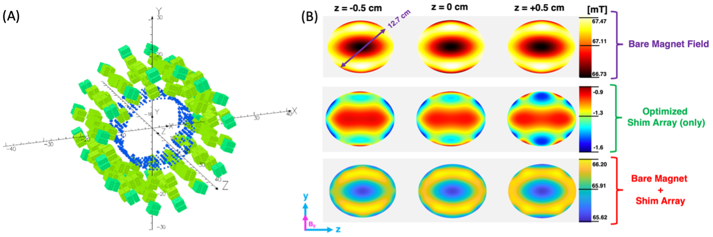
In our previous work, we used a genetic algorithm to optimize the radial positions of magnetic block-pairs to maximize the homogeneity of the magnet within a cylindrical 12.7 cm diameter, 1 cm long region of interest (ROI)6,7. We used 3D printed formers and high-coercivity ferromagnets (N40UH) to achieve an accurate field in a constructed, low aspect ratio (~1:1) magnet6.The constructed Halbach magnet requires B0 field adjustments for TRASE MR imaging. Simulations in Figure 2A show that the bandwidth over ROI is 32 kHz. Unfortunately, out-of-ROI volume is also excited, leading to frequency aliasing (red arrows in Figure 2) due to a lack of axial encoding capability.
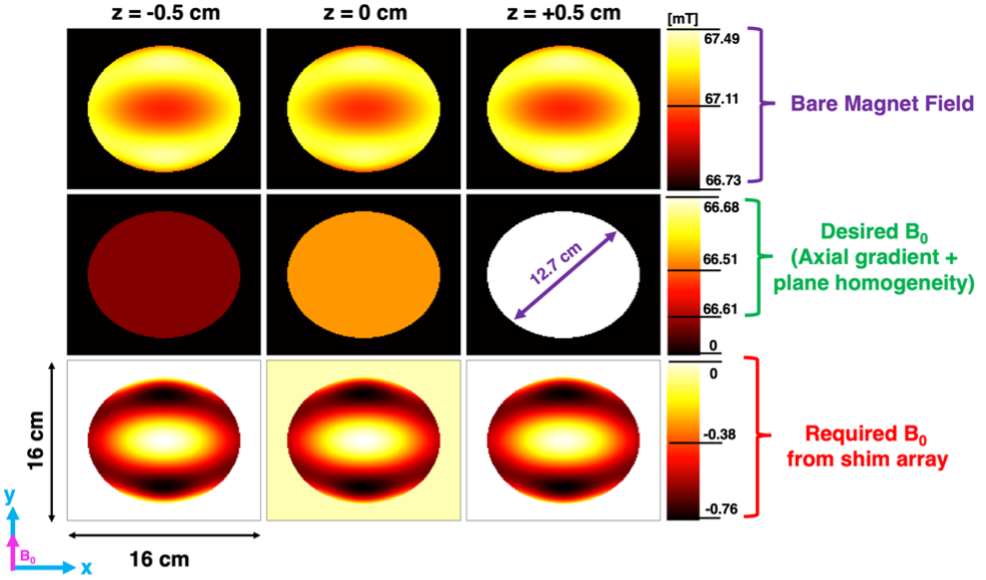
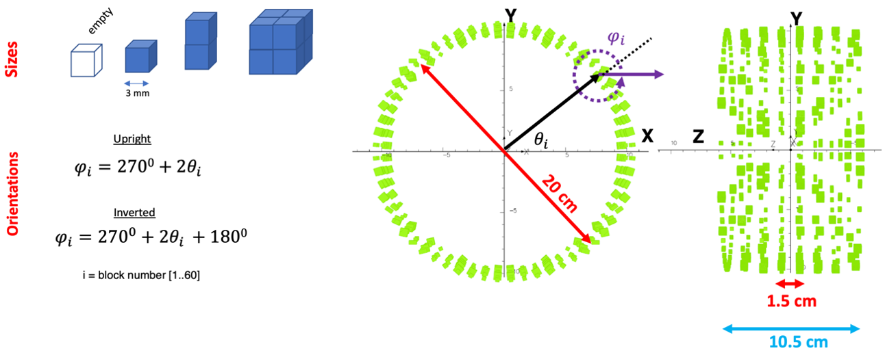
Our solution introduced an array of small permanent magnet blocks added to the Halbach magnet to remove unwanted fields. We optimized a permanent magnet shim array for block sizes and orientations aiming for an axial gradient (~7 mT/m) and improved in-plane homogeneity (peak-to-peak < 0.07 mT) (Figure 3). We applied a discrete genetic algorithm optimization (Global Optimization Toolbox, Matlab, MathWorks, USA) of eight coaxial rings, each consisting of 60 blocks (Figure 4). An automated process was used to simulate the field (Opera3D, Dassault Systèmes, France) using real BH curves for N40UH magnetic material for all possible block sizes, locations and orientations on a defined grid (Figure 4). The simulated field data was stored in a database and retrieved for fast optimization.
Results
The magnet shimming simulations showed that plane inhomogeneities were reduced by ~20% (ΔB0 = 0.74 mT for bare magnet; ΔB0 = 0.58 mT with the shim array) within an ROI comprising a cylinder volume of 12.7 cm diameter, 1 cm long (Figure 5). In addition, the shim array produces a 7 mT/m axial gradient at the geometric isocenter (Figure 5). Unfortunately, the quadratic axial profile is still present because the shim array is too short. Nevertheless, a smaller cylindrical region of ~ 3 cm diameter and 1 cm long could be used for TRASE imaging.Discussion
As shown in Figure 5B, most of the remaining inhomogeneity in the ROI is due to the original length truncation of the main magnet since the shim array spans only one-half the length of the Halbach magnet. Future shim array designs should use more rings and blocks along the entire Halbach magnets' length. Furthermore, the larger inner diameter (26 cm) of the bare magnets central rings provides even more space for additional magnetic pieces. This updated shim configuration will provide the genetic algorithm with more diversity (increasing the number of locations, sizes and orientations) to further improve B0.Conclusion
With the recent success of TRASE MRI system testing on a Falcon 20 parabolic flight14, B0 shimming of the magnet is a critical next phase for producing a TRASE MRI with high-quality MR images for use on the ISS. Therefore, based on the preliminary B0 simulations, this work shows that sufficient field improvements for TRASE are possible using an array of small permanent magnets optimized for size and orientation.Acknowledgements
This work was supported in part by the Natural Sciences and Engineering Research Council of Canada (NSERC) Discovery under Grant RGPIN-2020-04414.References
1. Williams D, Kuipers A, Mukai C, and Thirsk R. (2009). Acclimation during space flight: effects on human physiology. Canadian Medical Association Journal. 180(13) 1317-1323.
2. Kanas N. and Manzey D. (2008) Basic Issues of Human Adaptation to Space Flight. In: Space Psychology and Psychiatry. The Space Technology Library (Published jointly by Microcosm Press and Springer), vol 22. Springer, Dordrecht.
3. Barratt MR, Baker ES, and Pool SL. (2019). Principles of Clinical Medicine for Space Flight. Chapter 4.
4. Sarty GE, Scott A, Turek K, Liszkowski P, Sharp JC, and Tomanek B. (2014). A wrist MRI for the International Space Station. 65th International Astronautical Congress, Toronto, Canada. Published by the IAF.
5. Wald LL, McDaniel P, Witzel T, Stockmann JP, Cooley CZ. (2019). Low-cost and portable MRI. Journal of Magnetic Resonance Imaging, Vol. 52, Issue 3, pp. 686-696.
6. Purchase AR, Vidarsson L, Wachowicz K., Liszkowski P, Sun H, Sarty GE, Sharp JC, and Tomanek B. (2021). A Short and Light, Sparse Dipolar Halbach Magnet for MRI," in IEEE Access, vol. 9, pp. 95294-95303.
7. Purchase AR, Sarty GE, Vidarsson L, Wachowicz K., Liszkowski P, Sun H, Sharp JC, and Tomanek B. (2020). Design of a Permanent Magnet for MRI of the Ankle on the International Space Station. Proc. Intl. Soc. Mag. Reson. Med. 28: 1252.
8. Sun H, Yong S, and Sharp JC. (2019). The twisted solenoid RF phase gradient transmit coil for TRASE imaging. Journal of Magnetic Resonance. 299: 135-150.
9. Sun H, AlZubaidi A, Purchase A, and Sharp JC. (2019). A Geometrically Decoupled, Twisted Solenoid Single-Axis Gradient Coil Set for TRASE. Magnetic Resonance in Medicine. 83:4, 1484-1498.
10. Purchase AR, Palasz T, Sun H, Sharp JC, and Tomanek B. (2019). A high duty-cycle, multi-channel, power amplifier for high-resolution radiofrequency encoded magnetic resonance imaging. Magnetic Resonance Materials in Physics, Biology and Medicine. 32, 679-692.
11. T. O'Reilly, W. M. Teeuwisse, and A. G. Webb, (2019). Three-dimensional MRI in a homogenous 27 cm diameter bore Halbach array magnet,'' J. Magn. Reson., vol. 307, 106578.
12. C. Z. Cooley, P. C. McDaniel, J. P. Stockmann, S. A. Srinivas, S. F. Cauley, M. Sliwiak, C. Sappo, C. F. Vaughn, B. Guerin, M. S. Rosen, M. H. Lev, and L. L. Wald. (2021). A portable scanner for magnetic resonance imaging of the brain. Nature Biomed. Eng., vol. 5, no. 3, pp. 229 239, 2021.
13. McDaniel PC, Cooley CZ, Stockmann JP, and Wald LL. (2019). A target-field shimming approach for improving the encoding performance of a lightweight Halbach magnet for portable brain MRI. Proc. Intl. Soc. Mag. Reson. Med. 27: 0215.
14. Sarty’s USask team tests technology for MRI in space. (2021). University of Saskatchewan. https://news.usask.ca/articles/research/2021/sartys-usask-team-tests-technology-for-mri-in-space.php
Figures