3583
Design of an asymmetric spiral RF coil for RF spatial encoding1Department of Radiology and Biomedical Imaging, Yale University, New Haven, CT, United States
Synopsis
Gradients in B1 can be useful as a source of spatial encoding for low-field MRI. Here, an asymmetric spiral surface coil is introduced that generates an RF gradient around the coil. Simulations have shown that the shape of the B1 field can be controlled by adjusting the spacing between the wires. The measured B1 field of the asymmetric spiral coil shows that the RF gradient is generated near the coil as shown in the simulation results.
Purpose
Since RF energy absorption is low in low-field MRI, several groups have reconsidered spatial encoding methods that use RF1-3. With RF encoding, images can be obtained without using gradient coils and amplifiers, thereby potentially saving space and cost. One approach to RF encoding uses spatial variations in the amplitude of the B1 field to generate spatial varying encoding. In particular, Bloch-Siegert encoding imparts a phase shift that varies as |B1|2, so spatial variations in the B1 amplitude can impart a spatially varying phase shift that can be exploited for spatial encoding.One previous approach to spatial encoding with RF used a modified solenoid coil by adjusting the distance between wires1. While this enables RF encoding in one direction, it is not easy to combine with another coil for two-dimensional RF encoding. Another approach uses an RF surface coil, since the B1 of the surface coil becomes smaller with increasing distance from the coil2. However, since the B1 magnitude rapidly decreases as a function of the distance, SNR also drops rapidly. In this study, we introduce an asymmetric spiral surface coil that can overcome these shortcomings.Methods
Figure 1a shows a rectangular RF surface coil pattern that is widely used as an MR receive coil. Figure 1b and 1c show the patterns of the suggested asymmetric spiral RF coil with equidistant legs and non-equidistant legs, respectively. The magnetic field amplitude of these coils was calculated using the Biot-Savart law because the wavelength effect at 1 MHz is negligible. Then, the magnitudes of the magnetic field in the z-direction and its square were compared. Note that, the frequency shift is proportional to the square of the B1 magnitude when the Bloch-Siegert (BS) RF encoding is used2.Figure 2 shows pictures of the asymmetric spiral RF coil with non-equidistant legs. The coil was tuned and matched at 870 kHz with 4850 pF of the tuning capacitor and 680 pF of the matching capacitor. The B1 magnitude of the coil was measured using a 3D printer and digital oscilloscope1 while the coil is put together with the solenoid coil in the RF shield as shown in Fig. 2b. The RF shield was made by copper wire mesh and the solenoid coil was tuned and matched to 1 MHz and 50 ohms, respectively.Results
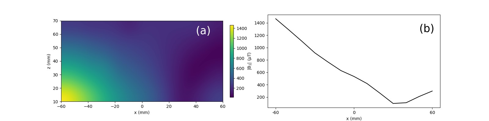
Figure 3 shows the calculated z-component (perpendicular to B0) of the B1 maps of the RF coils shown in Fig. 1. Both rectangular coil and asymmetric spiral coils generate B1 gradients in the z-direction. However, asymmetric spiral coils generate B1 gradient in x-direction as well, while the rectangular coil generates uniform B1 field inside the coil area in the x-direction. Figure 4 shows the B1 magnitude profile along the x-axis. B1 magnitude of the asymmetric coil with equidistant legs and square of the B1 magnitude of the asymmetric spiral coil with non-equidistant legs decrease linearly when x is between -100 and 100. Figure 5 shows the measured z-component of the B1 magnitude of the asymmetric spiral coil (Fig. 2).Discussion
We have shown that the asymmetric spiral RF coil generates greater spatial variation in B1 in the center of the coil compared to a circular coil design. Simulation results show that the shape of the magnetic field can be changed by adjusting the spacing between the rectangles. Using this method, the coil can be designed to be more suitable for BS-encoding. An asymmetric spiral coil was built and tuned at 870 kHz. The measured B1 field magnitude is decreasing in the x-direction, similar to the simulation result. This coil may also designed as part of a 2D plane array coil for 2D RF encoded MR imaging.Conslusions
It was demonstrated using both simulation and bench measurements that the asymmetric spiral coil generates a smoother gradually decreasing RF gradient above the coil. These asymmetric spiral coils can be effectively used to perform RF encoding with techniques such as Bloch-Siegert encoding.Acknowledgements
No acknowledgement found.References
1. J. B. Martin, C. E. Vaughn, M. A. Griswold, and W. A. Grissom, “Bloch-Siegert |B1+|-selective excitation pulses,“ in Proc. 29th Annu. Meet. Int. Soc. Magn. Res. Med., Virtual, May 15-20, 2021
2. R. Kartäusch, T. Driessel, T. Kampf, T. C. Basse-Lüsebrink, and U. C. Hoelscher, “Spatial phase encoding exploiting the Bloch-Siegert shift effect,” Magn. Reson. Mat. Phys. Biol. Med., vol. 27, no. 5, pp. 363-371, Oct. 2014.
3. R. T. Constable, C. Rogers III, B. Wu, K. Selvaganesan, and G. Galiana, “Design of a novel class of open MRI devices with nonuniform B0, field cycling, and RF spatial encoding,” in Proc. 27th Annu. Meet. Int. Soc. Magn. Res. Med., Montreal, Canada, May 10-13, 2019.
Figures
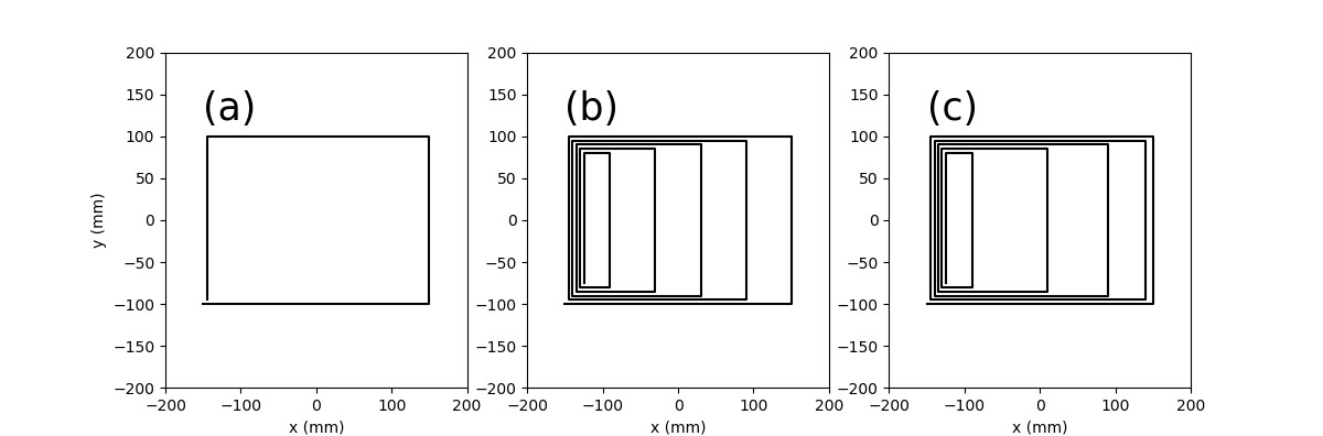

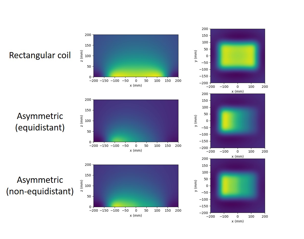

Figure 4. Profile of B1 (left column) and B1 squared (right column) in the x-direction for rectangular coil (top row), an asymmetric spiral coil with equidistant legs (middle row), and with non-equidistant legs (bottom row). |B1| of the asymmetric coil with equidistant legs is linear at the center of the coil and |B1|2 of the asymmetric coil with non-equidistant legs is linear at the center of the coil.