3580
A small loop makes a big difference: Modifying trajectory of epicardial leads substantially reduces RF heating of CIEDs in children during 1.5T MRI1Department of Biomedical Engineering, McCormick School of Engineering, Northwestern University, Evanston, IL, United States, 2Department of Radiology, Feinberg School of Medicine, Northwestern University, Chicago, IL, United States, 3Division of Cardiovascular-Thoracic Surgery, Ann & Robert H. Lurie Children's Hospital of Chicago, Chicago, IL, United States, 4Division of Cardiology, Ann & Robert H. Lurie Children's Hospital of Chicago, Chicago, IL, United States, 5A. A. Martinos Center for Biomedical Imaging, Massachusetts General Hospital, Boston, MA, United States, 6Division of Medical Imaging, Ann & Robert H. Lurie Children’s Hospital of Chicago, Chicago, IL, United States
Synopsis
Infants with congenital heart defects, inherited arrhythmia syndromes, and congenital disorders of cardiac conduction often require cardiac implantable electronic devices (CIEDs). Some infants receive a CIED within hours, or even minutes, of birth. The presence of an epicardial CIED is a relative contraindication for cardiac magnetic resonance imaging (MRI) due to the risk of RF heating. We present results of phantom experiments and electromagnetic simulations showing that a simple surgical modification in the trajectory of epicardial leads can reduce RF heating more than 40-fold during MRI at 1.5 T.
Introduction
Congenital heart defects (CHD) are the most common type of birth defect in the United States, affecting 1 in every 100 babies born per year 1. Infants with CHD often require cardiac implantable electronic devices (CIEDs), some implanted within hours, or minutes, from birth 2. The optimal approach to affixing a CIED to the heart of a young patient is to open the chest and sew the cardiac lead directly to the myocardium (“epicardial leads”) as opposed to passing it through veins and affix to the inside of the heart (“endocardial leads”). Unfortunately, once epicardial leads are implanted, the risk of RF heating results in a relative contraindication to MRI, which inhibits optimal imaging in young people 3. Here, we show that a simple surgical modification in the trajectory of epicardial leads can substantially reduce RF heating during MRI at 1.5 T. We designed and constructed a multi-material anthropomorphic pediatric phantom based on segmented MR images of a 29-months-old child and measured temperature rise ΔT at the tip of an implanted epicardial CIED during RF exposure at 1.5 T. We found that ΔT could be reduced on average by 40-fold when the epicardial lead looped was placed on the inferior surface of the heart as opposed to the anterior surface of the heart. Electromagnetic simulations confirmed the experimental results, showing that the coupling between MRI electric fields and implanted leads was substantially reduced in the case of inferior loop compared to an anterior loop. The results were robust against perturbations in lead positioning, suggesting that a simple easy-to-implement surgical modification can lead to a significant and reliable increase in MRI safety.Methods
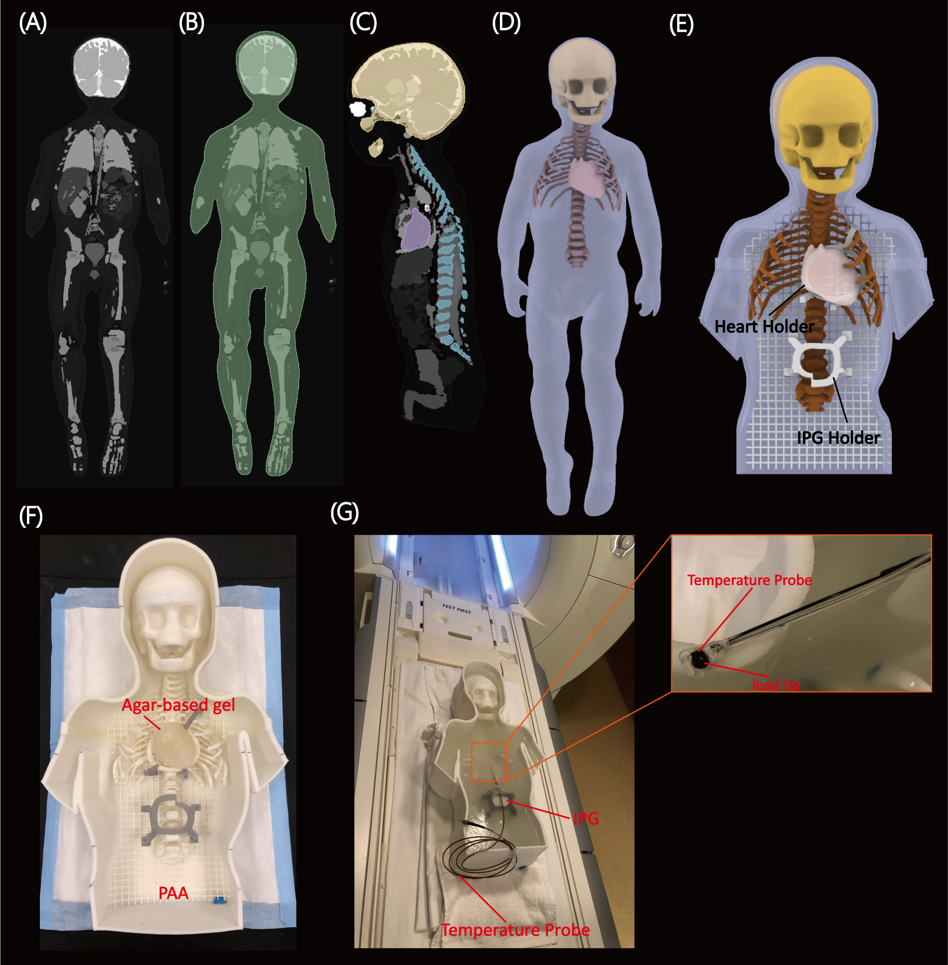
Phantom experimentsWe designed, and 3D printed a pediatric phantom consisting of a human-shaped container, skull, rib cage, and heart, based on MR images of a 29-month-old child (Figure 1). A Medtronic Azure™ XT DR MRI SureScan pulse generator was connected to a 35 cm epicardial lead (Medtronic CapSure® EPI 4965) and placed in the phantom's abdomen approximately 10 cm caudal to the center of the heart, in a typical position for epicardial pulse generators. Fiber optic temperature probes (OSENSA, Vancouver BC, Canada) were secured at the tip of the lead using threads (Figure 1G). The lead electrode was fixed to the surface of the heart phantom in a position analogous to the right atrial epicardium. RF heating was measured during 453 seconds of scanning with a high-SAR T1-TSE sequence (TE=7.3 ms, TR= 814 ms, B1+rms= 4.13μT).
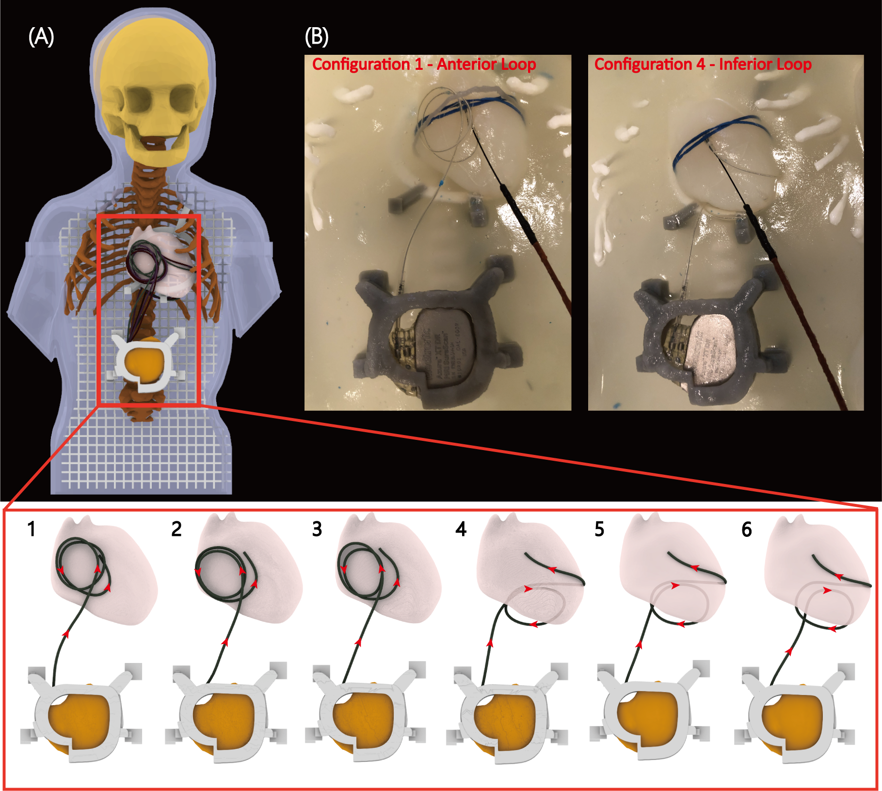
We investigated two distinct lead trajectories. In the first, the excess length of the lead was looped on the inferior surface of the heart (Figure 2B). In the second, the loop was placed on the anterior surface of the heart. Both techniques are used in pediatric surgical practice. To assess the sensitivity of results to variations in setup, each trajectory was implanted three times with small perturbations in the loop diameter and position (Figure 2A).
Electromagnetic simulations
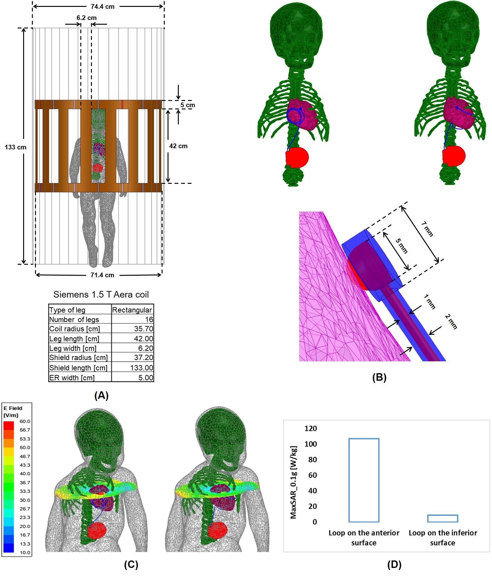
Electromagnetic simulations were implemented in ANSYS Electronics Desktop 2020 R2 (ANSYS Inc., Canonsburg, PA) with the same body model that was used to create the phantom (Figure 3A). The lead was modeled as a 35-cm insulated wire with a semi-sphere exposed tip positioned on the surface of the right atrium (Figure 3B). The body+CIED model was placed inside a shielded RF body coil with dimensions mimicking that of the Siemens 1.5 T Aera system. The maximum of 0.1g-averaged SAR around the lead's tip was recorded for each trajectory, for the input power of the coil adjusted to produce a mean B1+= 2μT on an axial plane (a common RF power limit for scanning in the presence of electronic implants).
Results
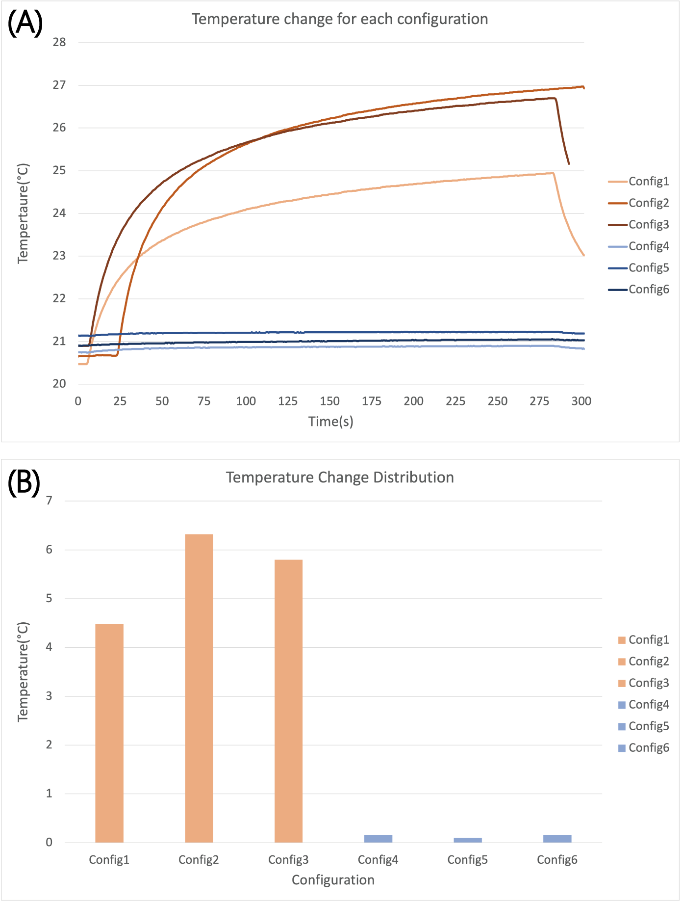
The measured temperature rise at the tip of the lead was 5.53±0.95 °C for trajectories with the excess loop placed on the anterior surface of the heart, compared to 0.14±0.03 °C for trajectories with the excess loop on the inferior surface of the heart showing a 40-fold reduction in RF heating (Figure 4). Simulations confirmed a substantial reduction in 0.1g-averaged SAR from 107 W/kg for loop on the anterior surface to 9 W/kg for the loop on the inferior surface of the heart.Discussion and Conclusion
Excessive tissue heating is the primary reason preventing patients with conductive implants from receiving MRI exams, especially those with elongated leads that are part of cardiovascular or neuromodulation devices. It is well established that the trajectory of an implanted lead and its orientation with respect to MRI electric fields substantially affects the RF heating 4, 5. The idea that the lead trajectory can be manipulated to potentially reduce RF heating was originally suggested for neuromodulation devices 6 and recently proved promising in patients with deep brain stimulation devices 7. Here we demonstrated that this simple yet highly effective technique could be adopted in children with epicardial leads to substantially reduce the risk of RF heating of the device during MRI at 1.5 T in a pediatric phantom model. If validated in biological systems, these mapping techniques could have a substantial impact on surgical technique and pre-surgical planning.Acknowledgements
Disclosures
This work was supported, in part, by in-kind lead donations from the Medtronic Corporation (Minneapolis, MN). K23HL130554 supported Dr. Webster.
References
1. CDC, Data and statistics on congenital heart defects (https://www.cdc.gov/ncbddd/heartdefects/data.html). Accessed July 2021.
2. Konta, L., et al., Twenty-seven years experience with transvenous pacemaker implantation in children weighing< 10 kg. Circulation: Arrhythmia and Electrophysiology, 2016. 9(2): p. e003422.
3. Bireley, M., et al., Cardiac Magnetic Resonance Imaging (MRI) in Children is Safe with Most Pacemaker Systems, Including Those with Epicardial Leads. Pediatric Cardiology, 2020. 41(4): p. 801-808.
4. Park, S.M., R. Kamondetdacha, and J.A. Nyenhuis, Calculation of MRI-induced heating of an implanted medical lead wire with an electric field transfer function. J Magn Reson Imaging, 2007. 26(5): p. 1278-85
5. Nordbeck, P., et al., Measuring RF-induced currents inside implants: Impact of device configuration on MRI safety of cardiac pacemaker leads. Magn Reson Med, 2009. 61(3): p. 570-8.
6. Baker, KB, et al., Reduction of Magnetic Resonance Imaging-Related Heating in Deep Brain Stimulation Leads Using a Lead Management Device. Neurosurgery, 2005. 57(4): p. 392-396.
7. Golestanirad, L., et al., RF-induced heating in tissue near bilateral DBS implants during MRI at 1.5 T and 3T: The role of surgical lead management. Neuroimage, 2019. 184: p. 566-576.
Figures