3579
Extension of Simple Safety Framework to Realistic Configurations1Cleveland Clinic, Cleveland, OH, United States
Synopsis
Implanted electrodes in patients used to treat movement disorders can induce unsafe heating in scanners above 1.5T. However, this patient population will likely benefit strongly from having the option of high field and ultra-high field scanners. To remedy this situation, we demonstrate a proof-of-concept that by carefully selecting the weights of the B1 shim on a Siemens 3T Prisma scanner, negligible temperature rise can be obtained using a T2-TSE sequence. We also show that when no temperature rise is obtained, the image quality is better and more homogeneous.
Introduction
Over 160,000 patients have DBS electrodes implanted, and this number is expected to keep increasing1. These patients will likely require MRI but are typically denied the potential benefit of UHF MRI due to safety concerns2. Developing safe UHF MRI protocols for DBS can be an arduous process, often involving computationally intensive simulations that are hard to tailor to individual patients. Eryaman et al.3 and Sadeghi-Tarakameh et al.4, demonstrated a simple geometric image analysis method that can be used to measure and mitigate RF induced currents on DBS leads at 3T and 7T, respectively. However, their work is limited to the case of a single electrode, whereas bilateral implantation of DBS electrodesis fairly common[. In this contribution, we demonstrate that safe operating regimes can be achieved in a two-electrode configuration.Theory
Implant-friendly (IF) modes3,4 are configurations that produce no measurable heating at the tip of the DBS electrode. In a system with multiple transmitters, each transmitter induces a current in the electrode. The contribution of each transmitter can be weighted so as to cause the currents to destructively interfere3,4. However, the formalism is, to our knowledge, limited to a configuration with a single electrode.We extend the formalism to examine the clinically relevant configuration of two electrodes. The relation between transmit power and induced current:
A1I1,1 + A2I1,2 < I1max
A1I2,1 + A2I2,2 < I2max
where Ai is the relative, complex amplitude of transmitter i and Ii,j is the current induced by transmitter j in electrode i. is the maximum safe current in electode i.
These equations suggest that if the number of transmitters exceeds the number of electrodes, currents can be nulled completely. If the number of transmitters equals the number of electrodes, there is no non-trivial solution in which current is nulled. However, it is possible in theory to find a solution that minimizes, in a least squares sense, the currents and heating across all electrodes.
Methods
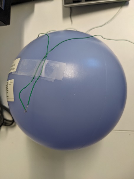
As a proof of principle of the formalism, we perform a search of the parameter space of transmit amplitudes and phases in a configuration with two transmitter and two electrodes and examine the resulting heating and image quality. Imaging was performed on a Siemens 3T Prisma (Siemens Healthineers, Erlangen, Germany) with a standard 20-channel head-neck receive-only array. The relative amplitudes and phases of the two transmit channels of the body coil were manipulated manually.To simulate bilaterally implanted DBS electrodes, two 0.8-mm diameter insulated copper wires with exposed tips were secured to the bottom of a container (figure 1) filled with gel prepared by following ASTM F2182-11a standard. Wire lengths of 85 cm were chosen to get maximum heating effect.5 Wires were chosen instead of DBS electrodes for ease of setup and to exaggerate heating, providing a worst-case scenario 6. Temperature changes were measured using fluoroptic temperature sensor (model m3300, Luxtron (Lumasense Technologies), Santa Clara, CA, USA) by securely tying probes to the exposed wire tips. A T2-TSE sequence was acquired to induce heating (axial, 240 mm x 240 mm FOV, 256 x 256 matrix, 32 slices, 4 mm thick, TE/TR=71/6470 msec, 212 Hz/Pixel bandwidth). A parameter space search of the complex amplitudes of the two was performed to find settings that produced the minimal temperature rise.
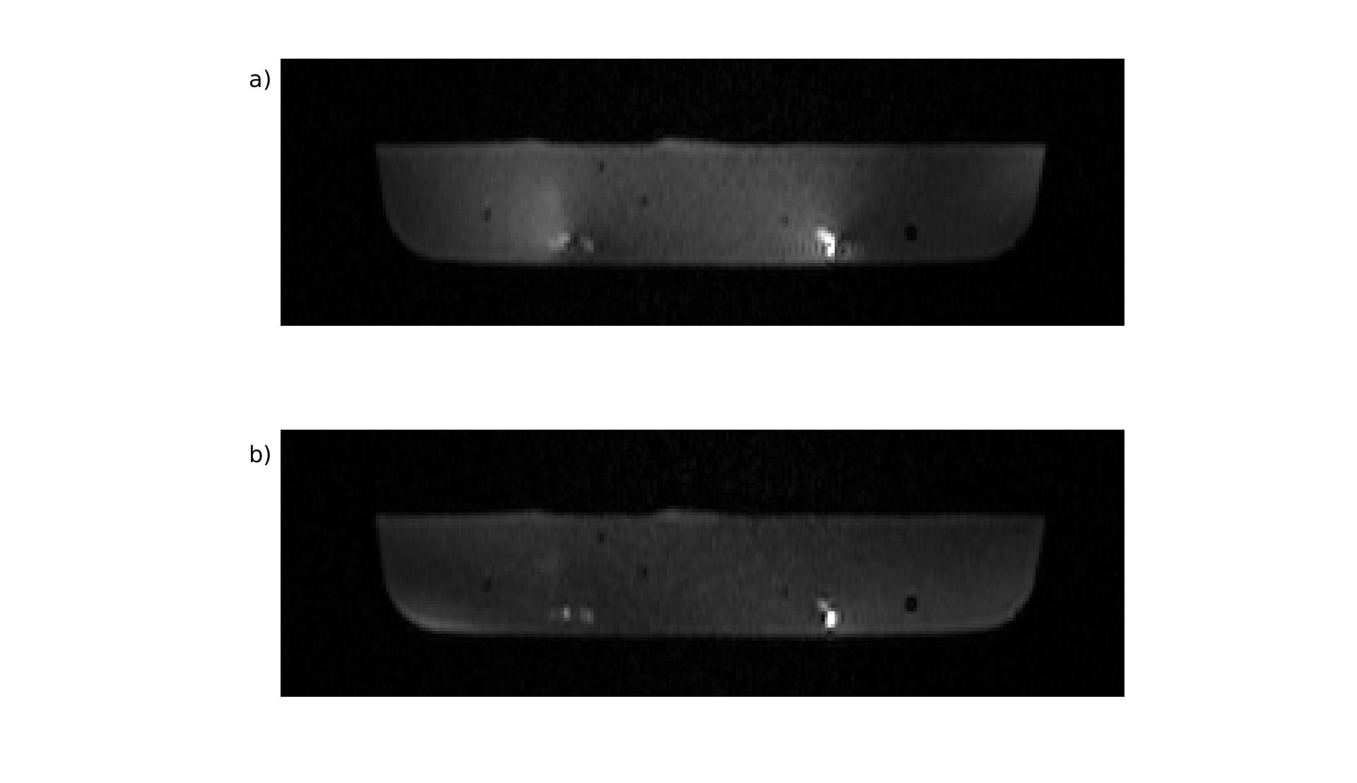
An MPRAGE sequence (axial, 256 mm x 256 mm FOV, 256 x 256 matrix, 120 slices, 1.2 mm thick, TE/TR=1.69/1900 msec, 530 Hz/Pixel bandwidth) was acquired to assess image quality. Two sets of weights were used: one that induced an unsafe temperature rise and another that induced no temperature rise and the image quality compared. These weights were found using the parameter space search described above.
Results
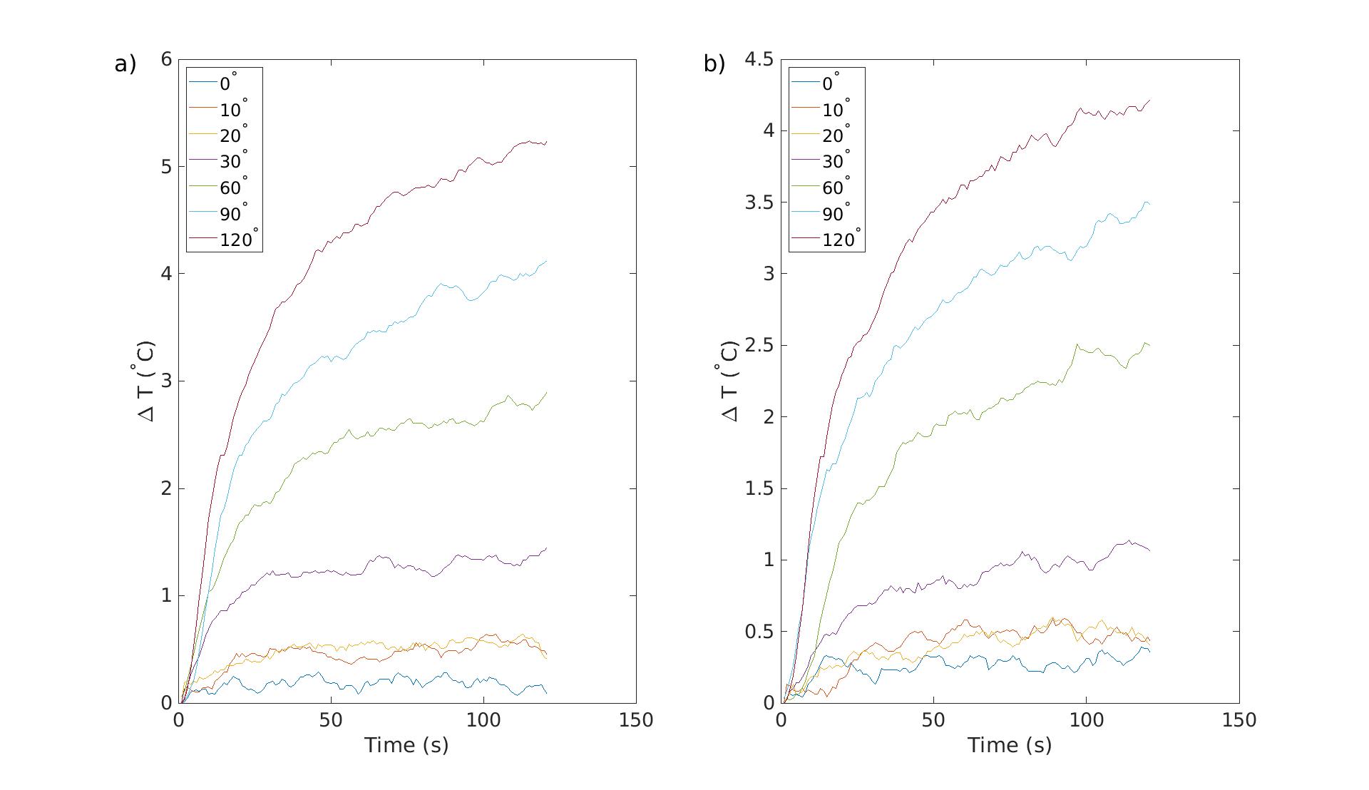
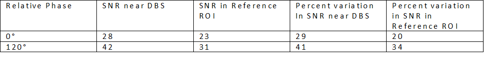
In Figure 2, we show the temperature response during the T2-TSE sequence for various complex weights of the two transmitters. The amplitudes of transmitter one on the B1 shim tab within the Adjustments tab was fixed at 0.8 whereas that of transmitter 2 was fixed at 0.4. The phase difference was varied between 0⁰ , 10⁰, 20⁰, 30⁰, 60⁰, 90⁰ and 120⁰ .To assess image quality, we calculated the signal-to-noise ratio (SNR) in a region surrounding (but not including) the DBS electrodes and in a reference ROI placed far from the electrodes. To calculate the noise, we measured the standard deviation in the noise values in an ROI placed in air. We also calculated the standard deviation in SNR values surrounding the DBS electrodes and in the reference ROI. These results are presented in Table 1.
The results of Table 1 suggest that the parameter space encompasses implant friendly modes. The implant-friendly mode shows lower inhomogeneity but at the cost of reduced SNR.
Conclusion
In this work, we have shown that safe scanning is possible when multiple electrodes are used. Future work will involve a careful comparison with the expected values of Equation 1 with values measured on the scanner to determine if that formalism can accurately describe the temperature rise measured with a phantom.Acknowledgements
No acknowledgement found.References
1. Andres M. Lozano, Nir Lipsman, Hagai Bergman, et al. Deep brain stimulation: current challenges and future directions. Nat Rev Neurol. 2019;15(3):148-160. doi:10.1038/s41582-018-0128-2
2. Alexandre Boutet, Clement T. Chow, Keshav Narang, et al. Improving Safety of MRI in Patients with Deep Brain Stimulation Devices Radiology 2020 296:2, 250-262
3. Eryaman, Y., Kobayashi, N., Moen, S., et al. A simple geometric analysis method for measuring and mitigating RF induced currents on Deep Brain Stimulation leads by multichannel transmission/reception. NeuroImage, 2019, 184, 658–668. https://doi.org/10.1016/j.neuroimage.2018.09.072
4. Alireza Sadeghi-Tarakameh, Lance DelaBarre, Nur Izzati Huda Zulkarnain, Noam Harel, Yigitcan Eryaman, Implant-Friendly Excitation Strategies for Imaging DBS Electrodes at 7T, Proceedings of the 30th Annual Meeting of ISMRM, Abstract 414, 2021
5. Yeung CJ, Karmarkar P, McVeigh ER. Minimizing RF heating of conducting wires in MRI. Magn Reson Med. 2007;58(5):1028-1034.
6. Bhusal B, Bhattacharyya P, Baig T, Jones S, Martens M. Measurements and simulation of RF heating of implanted stereo-electroencephalography electrodes during MR scans. Magn Reson Med. 2018 Oct;80(4):1676-1685. doi: 10.1002/mrm.27144. Epub 2018 Feb 21. PMID: 29468721.
Figures