3578
Study of B1 and SAR Field Distribution for loop coil with different bending angles at 3T1Biomedical Engineering, University at Buffalo, Buffalo, NY, United States
Synopsis
The aim is to investigate the RF field behavior of flexing loop coils as resonant elements in flexible RF arrays. Numerical modeling and simulation of a mechanically flexible single channel RF coil at different bending angles for 3T MRI are implemented to determine the best bending angle that will generate highest B1 magnetic field inside imaging area with least flux cancellation at center. Results include B1 magnetic and SAR field distribution of the coronal, sagittal and transverse planes of phantom at 9 bent angles. It also includes the comparative quantitative analysis of magnetic field at different biological samples.
Introduction
MRI provides exceptional soft tissue contrast with high temporal and spatial resolution compared to other imaging modalities1-5. The advances in the hardware includes the increase in the field strength, innovation in RF excitation and reception and enhancement in the gradient performance6-8. Radiofrequency coils are one of the most important part of the MRI system as they are mainly accountable for transmission and reception of MR signal and a primary device influencing image quality9-14. Recently, the interest in mechanically flexible RF coil arrays has grown rapidly in the MR community. The main benefit expected in comparison to rigid coils is a higher achievable signal-to-noise ratio (SNR) in case of strong variations of the targeted anatomy across patients.Methods
Flexibility of the RF surface coil enables the coil to be completely wrapped around patient’s body part. The closer the coil is to the body part, the better is the SNR. But when the two ends of the coil are almost parallel to each other at the extreme bending angle, magnetic flux cancel out at the center. This results in loss of data in center region of the phantom/imaged body part. To investigate this, the loop coil is bent at 8 angles from 20°-90°. Aim is to demonstrate distribution of the B1 magnetic field inside the phantom for different bending angles and find out the best bending angle that generates the most uniform magnetic field inside the phantom without magnetic flux getting cancelled at the center of the phantom. Model consist of an oval shaped phantom resembling human extremities such as wrist or ankle. The phantom dimensions are width 6cm, length 8cm and height 15cm. The behavior of model is studied at four different situations – one unloaded and three loaded cases. Phantom domain is assigned the dielectric properties of air in unloaded case. For loaded cases, the dielectric properties of tendon/ligament, muscle and prostate are used and their results are compared. The chosen dielectric properties of muscle are relative permittivity of 63.5ε, relative permeability of 1 and electrical conductivity of 0.71 S/m while that of tendon/ligament are 51.9ε, 1 and 0.49 S/m respectively and prostate with 72.1ε, 1 and 0.92 S/m15. The coil is made of copper in rectangular shape with thickness 0.3cm, height 10cm, length 35cm. Lumped element and lumped port are used to function as matching capacitor and excitation source. This whole assembly is then encircled within a large air sphere that function as scattering boundary condition. The frequency is set at 128MHz which is close to the Larmor frequency of hydrogen, 127.74Mhz at 3T MR system. Capacitance value is calculated by parametric sweep in the range of 0.2pF - 2pF with 0.1pF steps for better accuracy. The result is determined by S11 graph showing spike at 1.2pF. The B1 field is normalized by the input port power by the equation (abs(emw.Bx) + abs(emw.By))/(sqrt(emw.Pport_1)).Results
Results include the B1 magnetic and SAR field distribution inside the phantom at the central coronal, transverse and sagittal slice for bent angles ranging from 0° - 90° as shown in Figure[1]. Four cases with different dielectric properties assigned to the phantom are computed to study the relative change in the fields. In the unloaded case, it shows proportional increase in magnetic field distribution with increase in bending angles for all the planes as shown in Figure[2] a-c. The flux cancellation at the center of the slice is less prominent in this case. For all the loaded cases, magnetic field is clearly changed due to the effect of increase in dielectric properties values compared to unloaded case as shown in Figure[2] d-i. The SAR distribution show the similar change as that of magnetic field as shown in Figure[3]. Results of transverse plane graph did not point to a best bending angle as the graph showed gradual increase in magnetic field with increase in bent angle as shown in Figure [4] a, whereas Figure [4] b showing the results for selected area of central transverse plane show decrease in magnetic field after 80° bent. The flux cancellation at the center of the phantom slice can be seen clearly in the coronal and sagittal plane results in Figure[5] a and Figure[5] b respectively. They show a flat peak that illustrates the highest magnetic field generated in the range of 45°-65° coil bending angles and a gradual decrease in the magnetic field after 65° for the extreme bending angles that proves the concept of cancellation of magnetic flux at the center. This shows that complete wrapping of surface coils is not the ideal case for achieving a high SNR.Conclusion
We can gain high B1 magnetic field by using flexible RF coil over conventional rigid coil. Increased B1 field will ultimately improve SNR and excitation efficiency resulting in high resolution. But coil bending has to be restricted at certain angle, such that if we bend it to the extreme fit, we can clearly perceive magnetic flux cancellation.Acknowledgements
No acknowledgement found.References
1. J. J. H. Ackerman, T. H. Grove, G. G. Wong, D. G. Gadian, and G. K. Radda, "Mapping of metabolites in whole animals by 31P NMR using surface coils," Nature, vol. 283, pp. 167-170, 1980.
2. A. M. Abduljalil, A. Kangarlu, X. Zhang, R. E. Burgess, and P. M. Robitaille, "Acquisition of human multislice MR images at 8 Tesla," J Comput Assist Tomogr, vol. 23, no. 3, pp. 335-40., 1999.
3. G. Adriany et al., "Transmit and receive transmission line arrays for 7 Tesla parallel imaging," Magn Reson Med, vol. 53, no. 2, pp. 434-45, Feb 2005. [Online]. Available: http://www.ncbi.nlm.nih.gov/entrez/query.fcgi?cmd=Retrieve&db=PubMed&dopt=Citation&list_uids=15678527
4. R. Krug et al., "Ultrashort echo time MRI of cortical bone at 7 tesla field strength: A feasibility study," J Magn Reson Imaging, vol. 34, no. 3, pp. 691-695, Jul 18 2011. [Online]. Available: http://www.ncbi.nlm.nih.gov/entrez/query.fcgi?cmd=Retrieve&db=PubMed&dopt=Citation&list_uids=21769960
5. J. Kurhanewicz et al., "Hyperpolarized (13)C MRI: Path to Clinical Translation in Oncology," Neoplasia, vol. 21, no. 1, pp. 1-16, Jan 2019, doi: 10.1016/j.neo.2018.09.006.
6. X. Zhang, C. Wang, D. Vigneron, and S. J. Nelson, "Studies on MR Reception Efficiency and SNR of Non-resonance RF Method (NORM)," in Proceedings of the 17th Annual Meeting of ISMRM, Honolulu, USA, Honolulu, HI, 2009, vol. 17, p. 104.
7. X. Zhang, K. Ugurbil, and W. Chen, "A New RF Volume Coil for Human MR Imaging and Spectroscopy at 4 Tesla," in Proceedings of the 9th Annual Meeting of ISMRM, Glasgow, Scotland, Glasgow, Scotland, 2001, p. 1103.
8. X. Zhang, K. Ugurbil, and W. Chen, "Method and apparatus for magnetic resonance imaging and spectroscopy using microstrip transmission line coils. 7023209," US patent, 2006.
9. X. Yan, Z. Cao, and X. Zhang, "Simulation verification of SNR and parallel imaging improvements by ICE-decoupled loop array in MRI," Appl Magn Reson, vol. 47, no. 4, pp. 395-403, Apr 2016, doi: 10.1007/s00723-016-0764-x.
10. B. Wu, C. Wang, Y. Pang, and X. Zhang, "Comparison of SNR Calculation Methods for in vivo Imaging," Image, vol. 2, no. 1, pp. 1-2, 2010.
11. B. Wu and X. Zhang, "Capacitor/Inductor Decoupling and Its New Application to Microstrip Array," Proc. Intl. Soc. Mag. Reson. Med, vol. 19, p. 1860, 2011.
12. X. Yan, L. Wei, R. Xue, and X. Zhang, "Hybrid monopole/loop coil array for human head MR imaging at 7T," Appl Magn Reson, vol. 46, no. 5, pp. 541-550, May 1 2015, doi: 10.1007/s00723-015-0656-5.
13. X. Yan, Z. Xie, J. O. Pedersen, and X. Zhang, "Theoretical analysis of magnetic wall decoupling method for radiative antenna arrays in ultrahigh magnetic field MRI," Concepts in Magnetic Resonance Part B, vol. 45B, no. 4, pp. 183–190, 2015, doi: 10.1002/cmr.b.21312.
14. Y. Li et al., "A 24-channel head and spine array for 3T pediatric MRI under 3-year-old," in Proceedings of the 27th Annual Meeting of ISMRM, Monteal, Canada, 2019, p. 389.
15. https://itis.swiss/virtual-population/tissue-properties/database/dielectric-properties/
Figures

Figure[1]
Inset a show 8 Models for 8 bent angles, inset b show Transverse view of 8 bent angles, inset c show mesh representation of the models
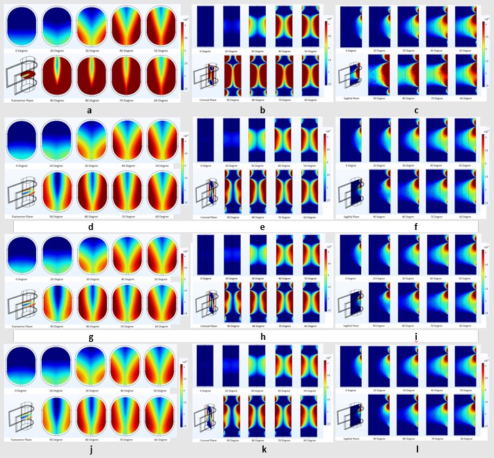
Figure[2]
Inset a-c shows B1 Field Distribution of transverse, coronal, sagittal plane of unloaded case, air, inset d-f shows B1 Field Distribution of transverse, coronal, sagittal plane of Tendon/ligament, inset g-i shows B1 Field Distribution of transverse, coronal, sagittal plane of Muscle, inset j-l shows B1 Field Distribution of transverse, coronal, sagittal plane of Prostate

Figure[3]
Inset a-c shows SAR Field Distribution of transverse, coronal, sagittal plane of Tendon/ligament, inset d-f shows SAR Field Distribution of transverse, coronal, sagittal plane of Muscle, inset g-I shows SAR Field Distribution of transverse, coronal, sagittal plane of Prostate

Figure[4]
Inset a shows B1 Magnetic Field vs Loop Coil Bending Angles Graph of Central Transverse Plane and inset b shows B1 Magnetic Field vs Loop Coil Bending Angles Graph of Selected area of Central Transverse Plane
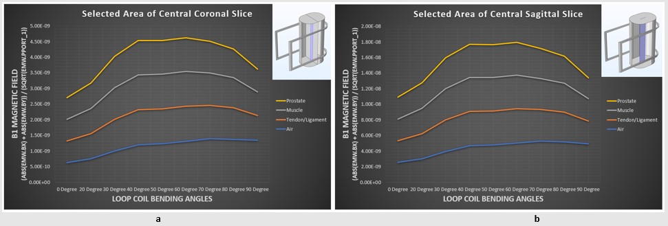
Figure[5]
Inset a shows B1 Magnetic Field vs Loop Coil Bending Angles Graph of Selected Area of Central Coronal Slice for all the cases and inset b shows B1 Magnetic Field vs Loop Coil Bending Angles Graph of Selected area of Central Sagittal Plane