3577
RF coil modeling with mechanical components: initial investigation
Xin Chen1 and Michael Steckner1
1Canon Medical Research USA Inc, Mayfield Village, OH, United States
1Canon Medical Research USA Inc, Mayfield Village, OH, United States
Synopsis
Electromagnetic modeling has been widely used to study MRI RF coils, but the coil model usually only consists of conductors and lumped elements. The impact of mechanical components (such as coil housing, patient table) has not yet been thoroughly investigated. This work showed that including mechanical parts in the model lead to noticeable changes of total B1 and E fields (up to 15% and 32% increase respectively in the central axial slice), peak SAR (22%), and coil input power (67%) calculations.
INTRODUCTION
Numerical electromagnetic (EM) modeling has been widely used to study MRI RF coils. The coil model usually only consists of conductors (e.g. birdcage endrings, rungs, and RF shield) and lumped elements. Recent study1 showed that adding a scanner bore wall to the model caused significant changes of peak SAR for a bore contact simulation but no detail was presented with respect to the bore. This work uses a simple model to demonstrate the impact of mechanical components (e.g. coil housing, patient table) in RF coil EM modeling.METHODS
A birdcage whole body transmit coil (16-rung high-pass birdcage, diameter 750mm, length 650mm, RF shield diameter 790mm, length 850mm)2,3 was modeled in Sim4Life (v6.2, ZMT). The model consisted of rungs, endrings, RF shield which were all PEC (perfect electric conductors), lumped elements (capacitors distributed in both endrings) and two voltage sources positioned in one endring. The coil was tuned to 127.6 MHz with 16.14pF capacitors in endrings. Coil tuning was performed by a multi-port broadband simulation. The resonance frequency was determined by comprehensive evaluation of a) FFT of B1 field at the coil center b) input impedance at the feeding ports and c) S parameters (Figure 1). A cylindrical shell (OD 750mm ID 730mm length 700mm) and a slab (550mm X 50mm Y 2000mm Z) were added to model materials between the body coil conductors and the patient, and the patient table respectively (Figure 2). While fiber reinforced plastic (FRP) is widely used as the materials for MR scanner and coil mechanical parts, its dielectric properties are rarely studied in the MR related frequency range and are expected to vary depending on the material vendor. As an initial study the dielectric properties of FR-4 (material used for PCB) from Sim4Life built-in material database were assigned to the cylindrical shell and the slab (relative permittivity 4 and electric conductivity 0.0038S/m). These values are similar to the dielectric properties of FRP reported in some literature (although not at MR frequency)4. The conductors of the birdcage coil tightly fit on the outer surface of the cylindrical shell without any air gaps, simulating copper traces on a real coil housing. Human model Visible Man5 was positioned in the coil to simulate abdomen imaging. There was no direct contact between Visible Man and the patient table. Simulations were repeated with the addition of the mechanical components: first the coil was tuned, and then Visible Man was added for abdomen imaging simulation.RESULTS
The coil’s resonance frequency shifted with the addition of the mechanical parts (from 127.6MHz to 121.6MHz). Changing all capacitors to 13.7pF tuned the coil back to 127.3MHz. Figure 3 shows total B1 and E fields in the central axial slice of Visible Man. Figure 4 shows 10g average SAR distribution in the coronal slice with global peak SAR. Table 1 summarizes coil input power and SAR results. All figures and numbers are normalized to 1uT B1+ magnitude in the central axial slice of Visible Man.DISCUSSION
The addition of mechanical components to a body coil model changed EM modeling results. The coil’s resonance frequency changed significantly. After retuning the coil to the same resonance frequency, total B1 and E fields, and SAR distribution showed noticeable differences. Pixel-by-pixel comparison of B1total showed variations from -13% to 15% (Figure 3c) and -34% to 32% variations for total E field (Figure 3f). The maximum increase of total E field magnitude is 17 V/m. Although the location of the global peak SAR did not change, its magnitude increased by 22% with the mechanical components. Coil input power increased by an even larger 67%. WB SAR dropped by <1%. These changes are expected since the mechanical components are all dielectric materials, which will interfere with the RF field. It was reported that FRPs are highly anisotropic and heterogeneous [6]. Detailed material properties may need to be investigated, and EM modeling may need to consider these mechanical components for more accurate results.CONCLUSION
Mechanical parts which exist on a real MR scanner but are not typically included in RF coil EM modeling can change results such as resonance frequency, coil input power, total B1 and E fields and SAR distributions. More complete and accurate coil model based on experimental validation is therefore needed.Acknowledgements
No acknowledgement found.References
- Tang M, Okamoto K, Yamamoto T, et al. Electromagnetic simulation analysis of an RF burn injury case occurred at the elbow-bore wall contact point. Proc. Intl. Soc. Mag. Reson. Med. 29 (2021): 2490
- Murbach M, Neufeld E, Kainz W, et al. Whole-body and local RF absorption in human models as a function of anatomy and position within 1.5T MR body coil. Magn. Reson. Med. 2014; 71(2):839-845.
- Murbach M, Cabot E, Neufeld E, et al. Local SAR enhancements in anatomically correct children and adult models as a function of position within 1.5 T MR body coil. Prog Biophys Mol Biol. 2011; 107(3):428-433.
- Nayak N, Kalagi G, Bhat V. Electrical insulating properties of natural fibre reinforced polymer composites: a review. International Journal of Engineering Research & Technology (IJERT), Vol.6 Issue 08, August 2017: 166-171.
- Collins CM and Smith MB. Calculations of B1 distribution, SNR, and SAR for a surface coil adjacent to an anatomically-accurate human body model. Magn. Reson. Med. 2001; 45: 692-699.
- Zhou J, Li Y, Cheng Li, et al. Dielectric properties of continuous fiber reinforced polymer composites: modeling, validation, and application. Polymer Composites. Vol 39, Issue 12 December 201: 4646-4655.
Figures
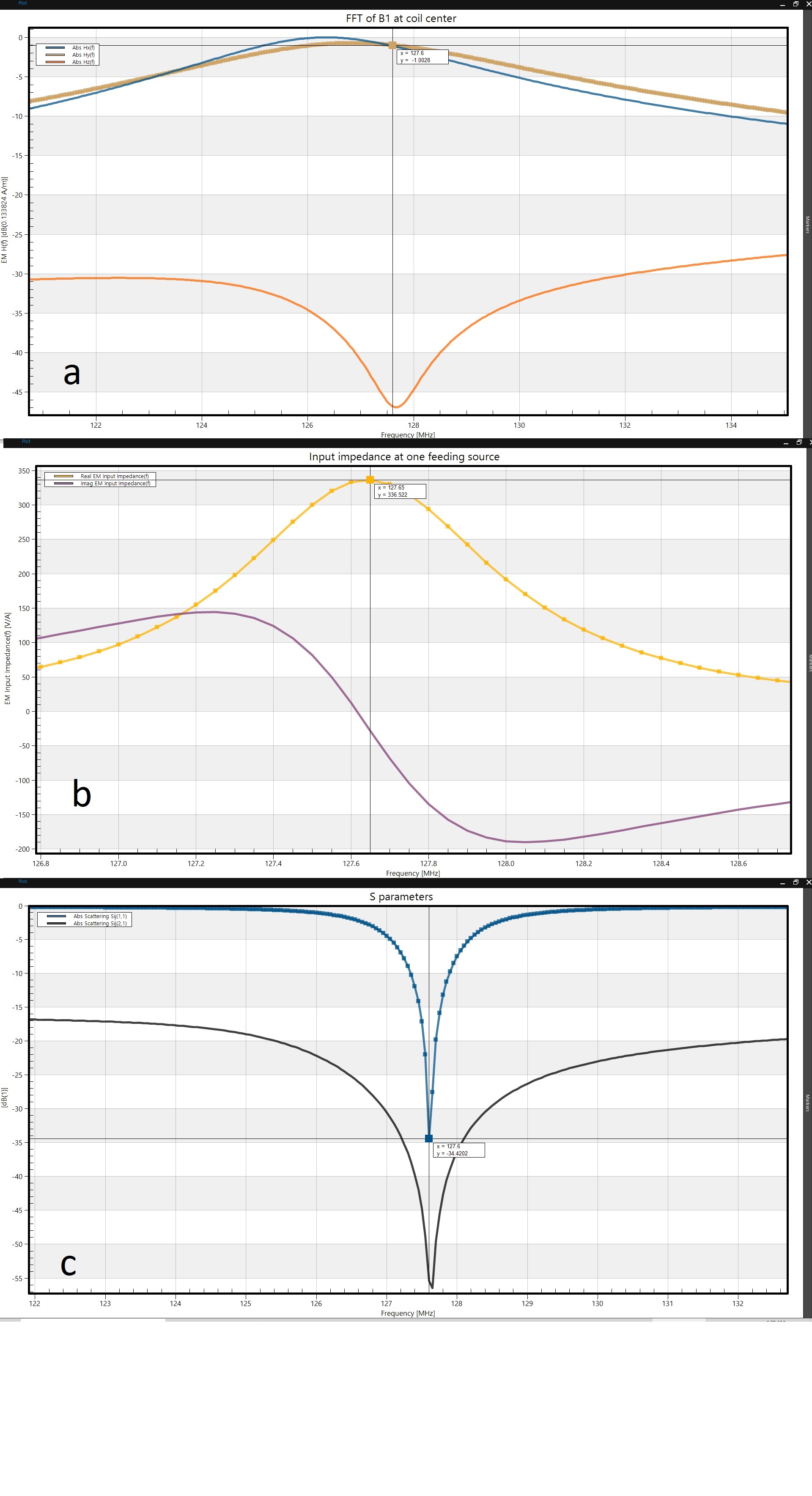
Figure 1. Tuning of the coil model as described in the text.
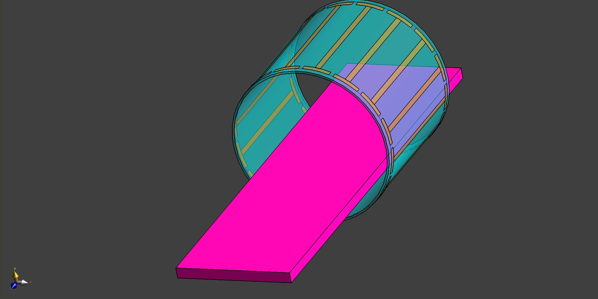
Figure 2. A birdcage coil model with coil housing, scanner bore wall, and a patient couch. The RF shield is not shown.
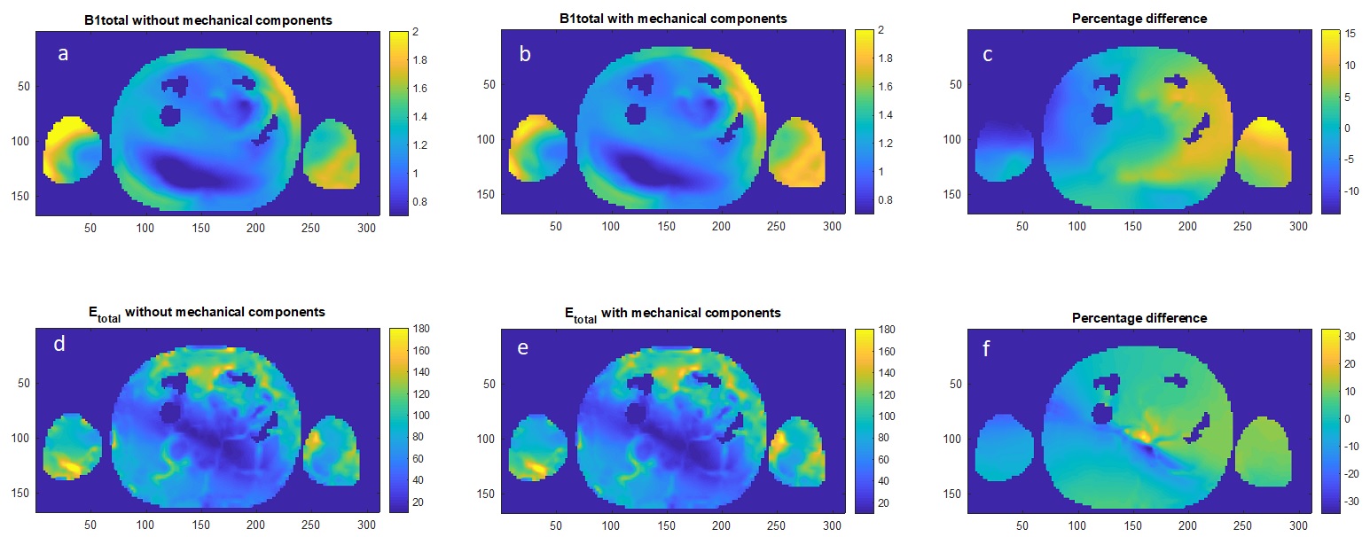
Figure 3. Total B1 and E fields distribution in the central axial slice of Visible Man with (b, e) and without (a, d) mechanical components in the model. The average B1+ magnitude within the slice was 1uT. (c) and (f) show the percentage difference. Note that for E field, although (d) and (e) appear similar, the difference (f) changed rapidly in the center of the body.
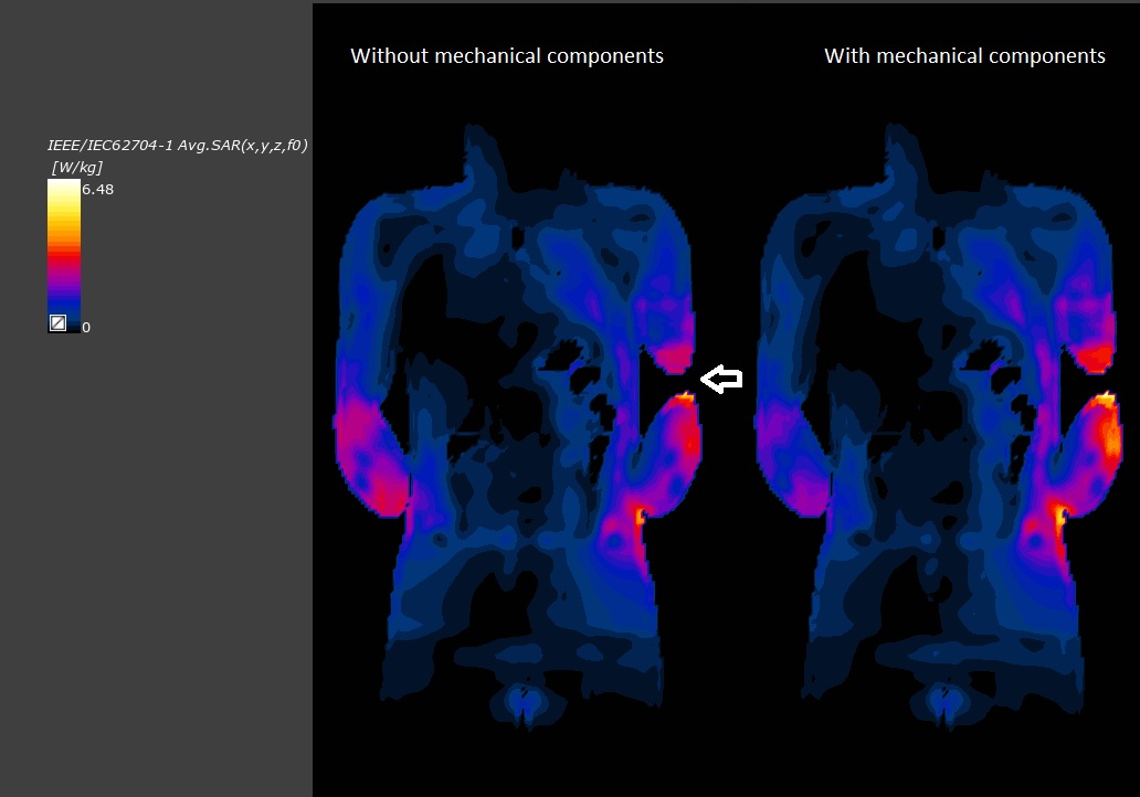
Figure 4. 10g SAR in the coronal slice where global peak SAR was located. The location of the global peak SAR (left elbow as indicated by the arrow) did not change.
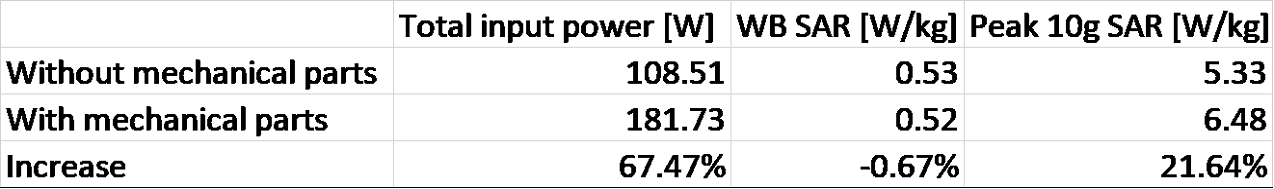
Table 1. Birdcage coil input power, WB and peak SAR for Visible Man when the average B1+ in the central slice is 1uT.
DOI: https://doi.org/10.58530/2022/3577