3440
Integrating a Unilateral MRI Scanner with a Small Animal Irradiator for Preclinical MR-Guided Radiation Experiments1Radiation Oncology, UT Southwestern Medical Center, Dallas, TX, United States
Synopsis
Magnetic Resonance-guided Radiation Therapy (MRgRT) has recently become available in human RT, however, this technology does not currently exist for preclinical systems. We propose a novel approach to develop and integrate an MR system with an existing small animal irradiator and report our ongoing progress constructing such a system. The MR system is comprised of a unilateral Halbach cylinder with permanent magnets and split gradient coils to prevent obstruction of the radiation beam while targeting a 4cm region of interest. Further development is ongoing for a split broadband RF coil and custom pulse sequences to maximize signal-to-noise.
Introduction
Small Animal Radiation Research (SARR) is important for the advancement of human radiation therapy (RT) by serving as a counterpart to allow for comprehensive preclinical studies on radiobiological mechanisms and the development of new radiotherapeutic strategies. SARR relies on dedicated irradiators to administer radiation under image guidance1. Cone beam CT is currently the most widely used image-guided modality, however, it is impeded by poor soft-tissue contrast, image artifacts, radiation exposure, and lack of real-time imaging capabilities2. Recently, magnetic resonance-guided RT (MRgRT) has become available in human RT3. This work proposes a novel approach to integrate a non-conventional MR scanner into a SARR platform for MR image guidance. We propose to use a unilateral MR design with an inhomogeneous magnetic field for imaging to mitigate geometric and electromagnetic interference between the MR scanner and the x-ray system. We will report our ongoing process of constructing such a system.Method
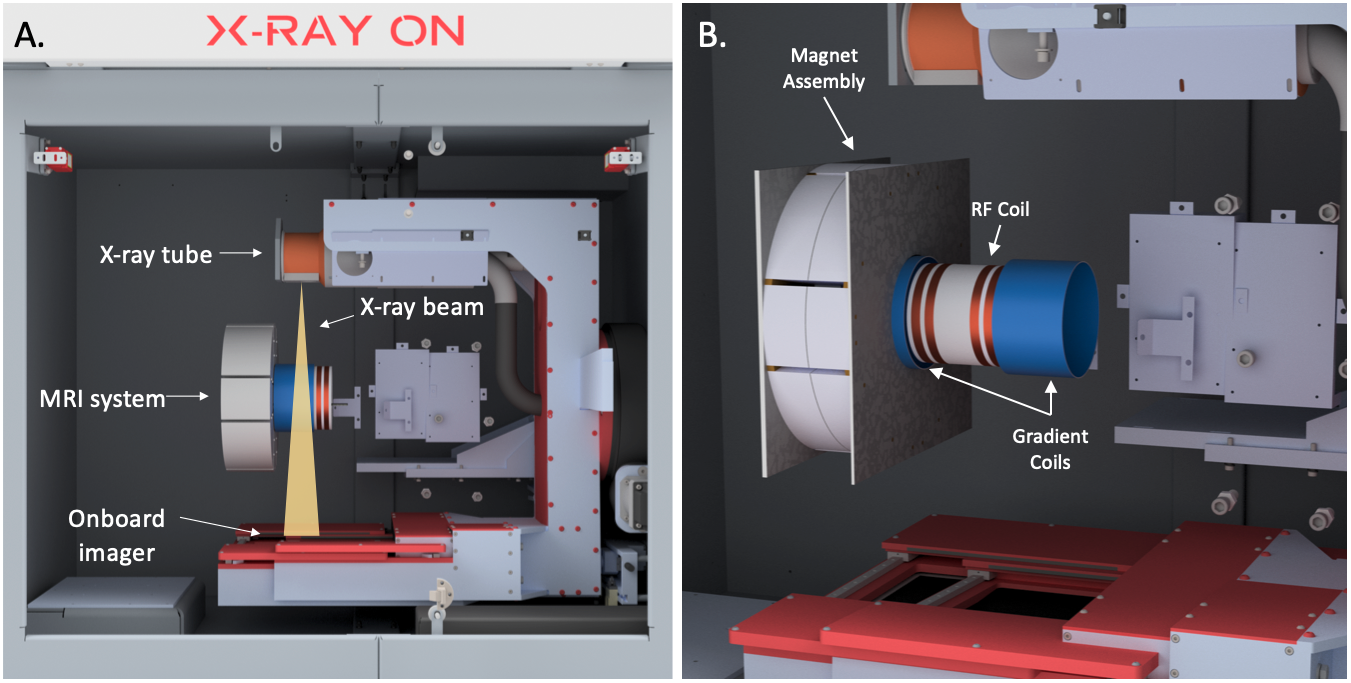
An illustration of our proposed MR-guided system is shown in Fig 1. The system consists of three primary components: the main magnet, gradient coils, and an RF coil. This system will then be integrated into a small animal irradiator in our laboratory.Main Magnet:
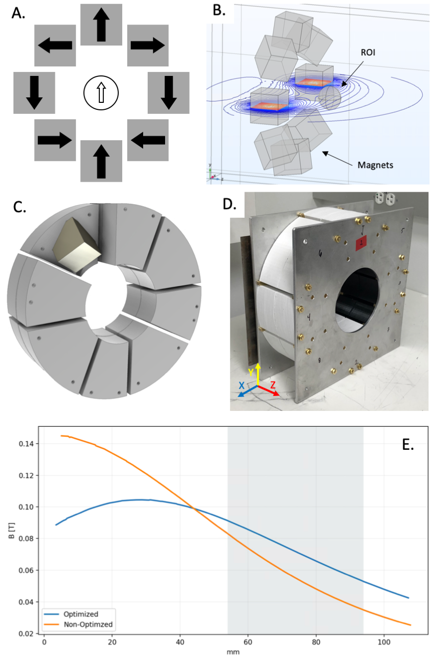
The main magnet was constructed by arranging 8 neodymium (Nd), N52-graded, 2 inch cubed, permanent magnets in a Halbach cylinder with a 12mm diameter opening for the irradiator couch to pass (Fig. 2A). To prevent obstruction of the radiation beam, the front surface of the Halbach cylinder is designed to be positioned 2cm from the isocenter of the radiation beam to allow for a spherical region of interest (ROI) of 4cm, as illustrated in Fig. 2B. To maximize the imaging field strength through the ROI, we implemented a genetic algorithm that optimized the magnetic flux density with respect to rotational freedom and radial size of the individual magnets4. The optimization results were simulated and verified using a finite element solver (Fig. 2B). 3D printed molds secured together between two aluminum plates were created to safely and accurately arrange the magnets (Fig 2C).
Gradient Coils:
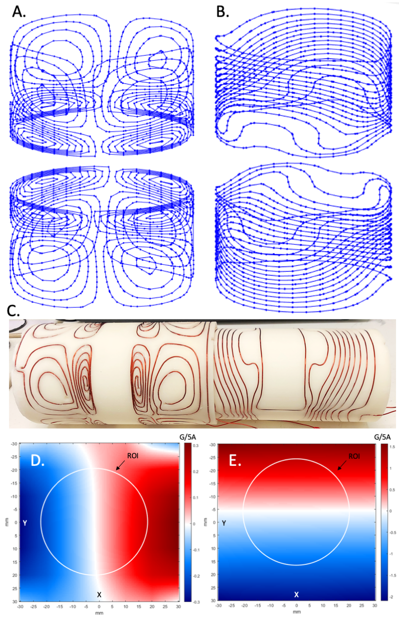
The main magnetic field can naturally be used for slice-select encoding along the axial, or Z-direction, requiring only two additional coils for frequency and phase encoding. We designed cylindrically-gapped coils to allow for the radiation beam to pass (Figs. 3A,B). The coil patterns were determined using a stream-function based targeted field method. The coil windings were constructed by 3D printing molds and wound with 18 AWG insulated magnet wire (Fig. 3C).
RF Coil:
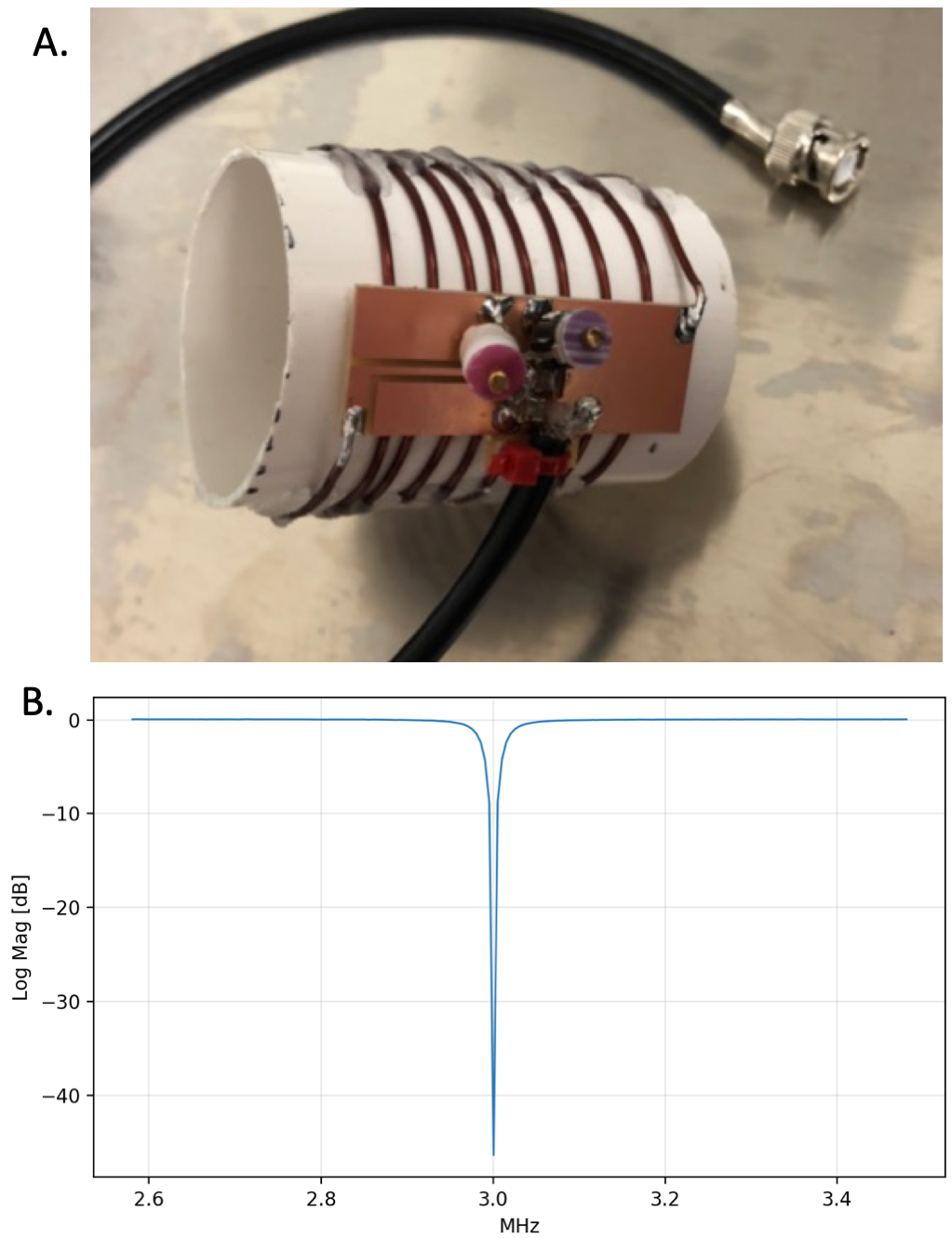
Due to the orientation of the main magnetic field perpendicular to the central axis, a solenoid coil was used for whole-body imaging. We constructed a transmit/receive coil tuned to 3 MHz for preliminary single-slice imaging (Fig. 4A). Ongoing work consists of a split RF coil design to prevent attenuation of the radiation beam.
Imaging Console:
We used our bench-top spectrometer to control the gradient coils driven by two homemade amplifiers capable of 150V/120A, and the RF coil with a 2kW broadband amplifier. We programmed a spin-echo pulse sequence and are currently developing custom fast spin-echo and Carr-Purcell-Meiboom-Gill pulse sequences to alleviate dephasing caused by the permanent gradient field and to minimize signal loss.
Simulation of Image-formation Process:
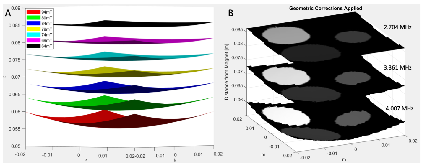
We plan to use the monotonically decaying permanent magnetic field for slice-selection, thus requiring the imaging process to sequentially acquire a set of 2D images, each at a given RF frequency. As the field distribution is known based on measurement, the RF frequency defines a 2D surface in the 3D space with the resulting reconstructed MR image bound to this curved surface (Fig. 5A). Once images on these surfaces are acquired, we can then resample them to a volumetric image defined on the Cartesian coordinates.
Results
The magnet optimization determined a maximum field strength of ~105mT with an effective field strength of 72mT at the isocenter. We were able to achieve up to a 47% increase in field strength with the optimized solution when compared to the non-optimized Halbach cylinder arrangement (Fig. 2E). Our measurements agreed with the finite element solution within <1% difference. The gradient linearity is shown in Figs. 3D,E. The coil resistances of Gx and Gy were 0.16 Ω and 0.23 Ω with inductance values of 19 µH and 13 µH respectively. The constructed RF coil has an S11 reflection coefficient <-45dB for >99% power delivery (Fig. 4B). Simulations of this reconstruction process were completed for a digital phantom with cylinders embedded in a cube that is 4cm in size. The acquired images are defined on 2D curved surfaces with RF frequencies of 4.00, 3.36, and 2.70 MHz, and shown in Fig. 5B.Discussion
One unique challenge in this MRI system is the permanent gradient along the Z-direction which spans from 53mT to 91mT, resulting in a wide bandwidth of ~1.7 MHz. We are currently designing a broadband tunable coil that can be electronically stepped to sweep the central frequency and span the resulting bandwidth.Conclusions
We proposed a novel approach for MR-guided SARR. We have completed the majority of individual components and are in the process of integrating them to form the MR system.Acknowledgements
This work was supported in part by the National Cancer Institute (Grant No. R37CA214639) and the Cancer Prevention and Research Institute of Texas (Grant No. RP200573).References
1. F. Verhaegen, P. Granton and E. Tryggestad Physics in Medicine & Biology, 56 (12) (2011), p. R55
2. D.A. Jaffray, J.H. Siewerdsen, J.W. Wong and A.A. Martinez Physics, 53 (5) (2002), pp. 1337-1349
3. B. Raaymakers, I. Jürgenliemk-Schulz, G. Bol, M. Glitzner, A. Kotte, B. Van Asselen, J. De Boer, J. Bluemink, S. Hackett, M. Moerland et al. Physics in Medicine & Biology, 62 (23) (2017), p. L41
4. C. Reeves, J.E. Rowe, Genetic algorithms: principles and perspectives: a guide to GA theory, Vol. 20, Springer Science & Business Media, 2002.
Figures