3338
RF shielding designs for birdcage coils for high-resolution animal fMRI at 9.4T1Department of Biomedical Engineering, Vanderbilt University, Nashville, TN, United States, 2Vanderbilt University Institute of Imaging Science, Vanderbilt University Medical Center, Nashville, TN, United States, 3College of Nuclear Equipment and Nuclear Engineering, Yantai University, Shandong, China, 4Department of Radiology and Radiological Sciences, Vanderbilt University Medical Center, Nashville, TN, United States, 5Department of Physics and Astronomy, Vanderbilt University, Nashville, TN, United States, 6Department of Molecular Physiology and Biophysics, Vanderbilt University, Nashville, TN, United States
Synopsis
RF shields are key components of volume coils, but they may cause imaging distortions and the significant heating. The effects of different shielding strategies were evaluated for a birdcage coil used to image animals at 9.4T. Three shields with various thicknesses and two shields with different slot patterns were comparatively investigated ed in terms of performance and temperature rise during fMRI acquisitions.
Introduction
High resolution functional imaging of animal brains can be limited in practice by imaging distortions and heating [1][2]. Birdcage coils are widely used in preclinical MRI as they perform well, allow for quadrature drive, and can provide a homogeneous transmit field [3]. Unlike in larger bore scanners, an RF shield is essential to avoid strong cross-talk with gradient coils that are in close proximity. However, gradient switching induces eddy currents that may cause imaging distortions and resistance heat on shield and coil. We investigated the performance of different designs of RF shields on a birdcage coil used for high resolution functional MRI of small primates at 9.4T.Materials and Methods
a. Birdcage coil with removeable RF shield:To ease the setup for comparisons, a birdcage coil was designed to allow for a removeable RF shield, as shown in Figure 1. This is an 8-rung high-pass design, with a diameter/length of 7.5/7 cm. Remote tuning rods were mounted on all trimmer capacitors to ensure that the coil is tuned and matched for each scenario.
b. RF Shield constructions:
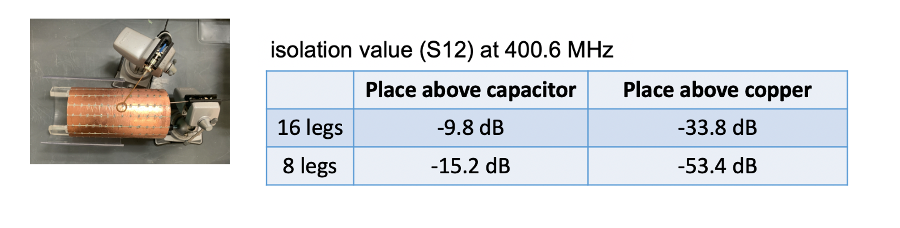
Five RF shields were built on 20-cm-long and 11.5-cm-diameter fiberglass tubes. Three shields were made from solid copper foil with different copper thicknesses (35μm, 9 μm, and 4 μm). The other two shields were made from segmented 35-μm-thickness copper foil with 8 or 16 slots. Fifteen discrete capacitors (1000 pF) were soldered across each slot for RF connection.
c. Shielding effectiveness:
The shielding effectiveness at 400.6 MHz was measured with a pair of 1-cm-diameter sniffer probes. Two sniffers were fixed in place, one inside the shield and the other outside the shield. The shielding effectiveness was evaluated as the transmission coefficient (S21) between the two sniffers, with S21 calibrated to 0 dB without the presence of the shield. For slotted shields, the shielding effectiveness was measured with sniffers close to the slots or close to the copper foils.
d. MR imaging performances:
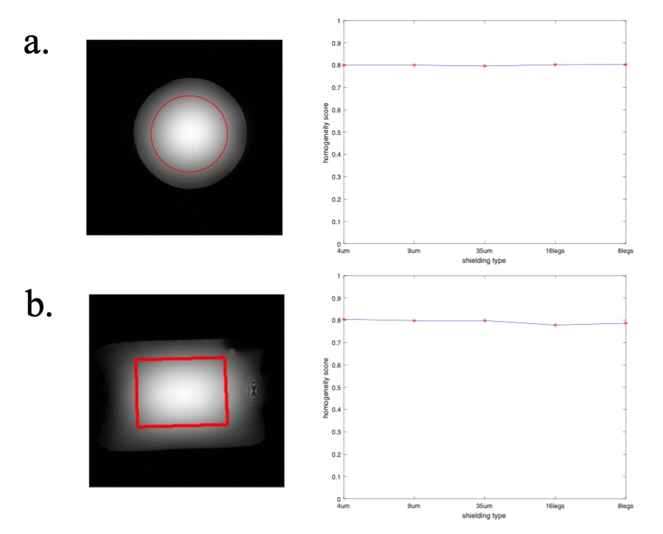
To assess the effect on SNR, low flip angle (LFA) GRE images were acquired on an ex-vivo squirrel monkey brain. RF shields may induce eddy currents which cause image distortions, low temporal SNR (tSNR) and temperature increases in EPI acquisitions for functional MRI. Two kinds of GE-EPI scans were performed, lower in-plane resolution (0.86×0.86 mm2) and higher in-plane resolution (0.43×0.43mm2). The gradient strengths and durations for low-resolution were 29.99 G/cm, 0.356ms (slice selection);18.26G/cm, 0.152ms (readout) and 17.98G/cm, 0.152ms (phase encoding); For high-resolution these were 29.99 G/cm, 0.356ms (slice selection); 25.5 G/cm, 0.216ms (readout) and 25.31G/cm, 0.216ms (phase encoding); Both have same blip settings (6.10G/cm, 0.056ms) and ramp time (44μs). A temperature probe was attached to the outer surface of the shield during EPI acquisitions to record the temperature rise. As noted in Doty et al [4], the slotted shield might affect the quadrature performance of a birdcage coil and reduce the field inhomogeneity. To ascertain whether our RF slotted shields have the same issue, we calculated the homogeneity on large-FOV LFA GRE images of a saline water phantom.
Results
a. Shielding effectiveness:All unslotted shields provide excellent isolation up to ~-53dB. For the slotted shield, the shielding effectiveness drops near the slots, especially for the 16-slot case, which would lead to non-negligible crosstalk with the outer environment and lower SNR.
b. MR imaging performances:
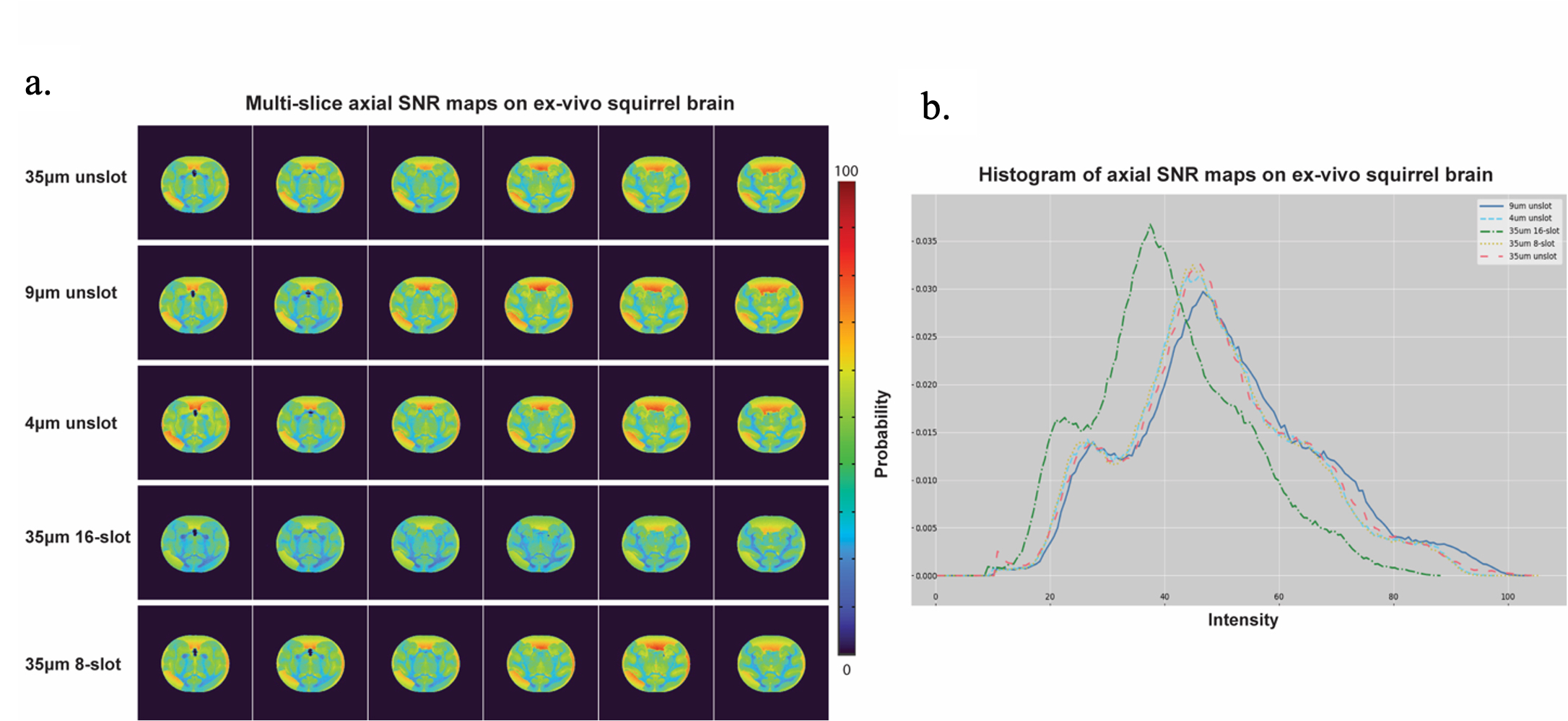
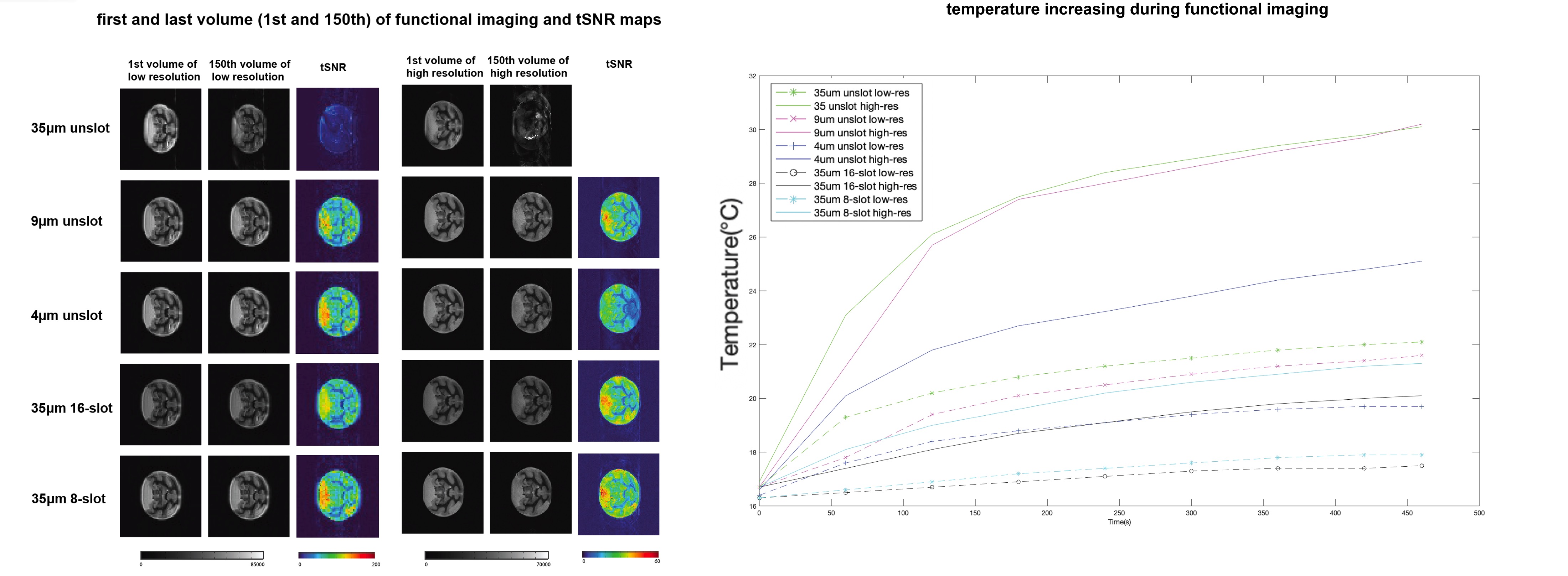
Figure 3 shows the multi-slice SNR maps. The 16-slot shield exhibits notable SNR decrease compared to that of other shields, which could be attributed to the low shielding effeteness. The temporal SNR (tSNR) of each functional imaging run and its corresponding temperature increase are shown in the Fig. 4. Except for the 35μm shield, other shields show no apparent ghosting in either low-res or high-res EPI scans. As expected, thinner copper and more slots lead to lower temperature increases. Overall, for the unslotted shields, 9 μm thickness is efficient and there is no need for ultrathin copper (such as 4μm) which is not easily available and has a higher cost. For the slotted shields, having more slots does not always mean better performance owing to the decrease shielding effectiveness. For this study, 8-axial slots are a good compromise that produces similar SNR compared to the unslotted shield and even slightly higher tSNR compared to the 16-slot shield. Fig. 5 plots the imaging homogeneity over 35mm diameter circle area (axial) and 40×30mm2 rectangle area (coronal). The slots do not significantly affect the field homogeneity or the quadrature performance.
Conclusions
Various RF shields with different copper thicknesses and slot patterns were investigated through bench tests, structural and functional MRI at 9.4T. We found that an unslotted RF shield made of 9-μm-thick copper foil already exhibits excellent SNR and tSNR, with no need for high-cost 4-μm-thick copper. Even for standard 35-μm-thick copper foil, one could use an 8-slot design to achieve similar performance.Acknowledgements
This work was supported by NIH grant NS078680, NS092961 and DOD grant W81XWH-17-1-0304. Zhangyan Yang and Ming Lu contributed equally to this work. The authors thank Dr. Yue Zhu for the help with RF isolation test.References
[1] M. E. Ladd et al., “Pros and cons of ultra-high-field MRI/MRS for human application,” Progress in Nuclear Magnetic Resonance Spectroscopy, vol. 109. Pergamon, pp. 1–50, Dec. 2018.
[2] F. Fiorillo, “Measurements of magnetic materials,” Metrologia, vol. 47, no. 2, 2010.
[3] C. E. Hayes, W. A. Edelstein, J. F. Schenck, O. M. Mueller, and M. Eash, “An efficient, highly homogeneous radiofrequency coil for whole-body NMR imaging at 1.5 T,” J. Magn. Reson., vol. 63, no. 3, pp. 622–628, Jul. 1985.
[4] F. D. Doty, G. Entzminger, J. Kulkarni, K. Pamarthy, and J. P. Staab, “Radio frequency coil technology for small-animal MRI,” NMR Biomed., vol. 20, no. 3, pp. 304–325, May 2007.
Figures