3319
An 8-Channel Shielded Transceiver Coil for Carotid Artery imaging at 7T1McConnell Brain Imaging Centre, Montreal Neurological Institute, McGill University, Montreal, QC, Canada, 2Siemens Healthcare Limited, Montreal, QC, Canada, 3Centre for Functional and Metabolic Mapping, Western University, London, ON, Canada
Synopsis
An 8-channel shielded transmit/receive RF array has been designed and fabricated for imaging the carotid arteries at 7T. The array, similar to that presented in Ref. [1], consists of four overlapping surface loops per side. In addition to the Ref. [1], we have also added two RF shields per side with DC blocking capacitors to mitigate eddy currents. To ensure robust safety of the 7T pTx coil, local SAR matrices, and the commensurate virtual observation points (VOPs), were calculated for online SAR supervision [2,3]. Finally, the phase and amplitude of each channel have been optimized to achieve maximum B1+ homogeneity.
Introduction
High resolution images of the carotid artery bifurcation, that have a high rate of plaques, are essential to diagnosis and follow up many diseases like Takayasu's arteritis [4].Surface RF coils and phased-array coils in particular [5] can obtain high resolution images of atherosclerotic plaques in the carotid artery, especially at ultra-high field (7 T and above). Since whole-body transmit coils are not standard on 7-Tesla MR systems, it is necessary to design either a transceive coil for both transmit and receive or disparate transmit and receive coils.
In this work, for imaging the human carotid artery at 7T with the Siemens 7T Terra scanner in parallel-transmission (pTx) mode, we present an optimized 8-channel transmit-receive carotid coil array to achieve high B1+- efficiency and minimum SAR (in CP+1 mode) for both left and right carotid imaging at 7T, using CST Microwave Studio [6].
Materials and Methods
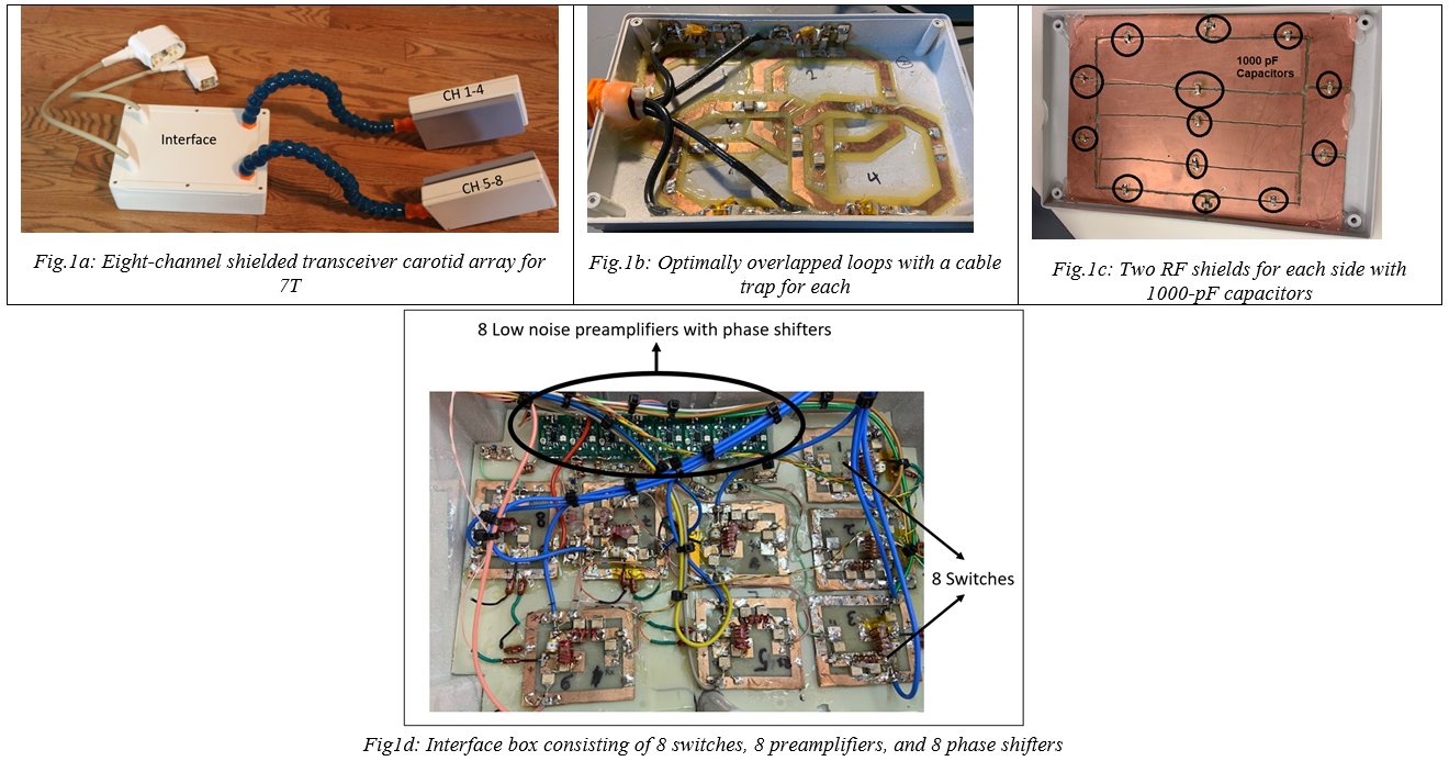
The coil (Fig.1a) consists of eight transmit-receive array elements and an interface box.Each side (left/right) has four overlapped loops (with a cable wave trap at the input of each) that are geometrically optimized to minimize mutual coupling (Fig 1b). One cable trap has been used for each channel. Each side has an RF shield with 1000-pF capacitors to mitigate eddy currents (Fig 1c).
Simulations were performed In CST Microwave Studio to optimize (i) the distance between the back shield and the loops on each side, and (ii) the dimension of each loop and overlap to maximize B1+-efficiency and minimize the Siemens K-factor (SAR/accepted power) for the eight-channel carotid coil when loaded with the Gustav body model in CST.
Each loop was tuned to the 1H operating frequency (297.2 MHz). Additionally, eight transmit/receive switches were incorporated to allow for switching between transmit and receive modes in the interface box (Fig. 1.d). Eight “Wan Tcom“ preamplifiers [7] were also incorporated into the interface box for individual amplification (Fig. 1.d).
In order to have optimal preamplifier decoupling, a phase shifter was included at the input port of each preamplifier.
Results and Discussion
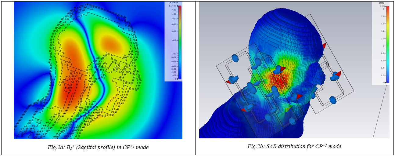
The coil was simulated, fabricated, and finally tested on a standard 7-L Siemens phantom (per 1000g H2O dist: 3,75g NisO4 x 6 H2O + 5g NaCl), SAM Head phantom V4.5 [8] and afterwards in vivo imaging of the carotid for a healthy volunteer.Results of the EM simulations (Fig.2) show the B1+ efficiency and SAR distribution within a CST anatomical model (Gustav) [6] of a human head when transmitting in CP+1 mode.
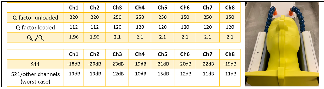
The maximum B1+ efficiency was 0.53 [μT/sqrt{W}] and the peak 10-g-average SAR over the accepted power was 0.086 kg-1 when transmitting in CP+1 mode. Fig 3. Shows the workbench performance when the coil was loaded with the SAM phantom [8].
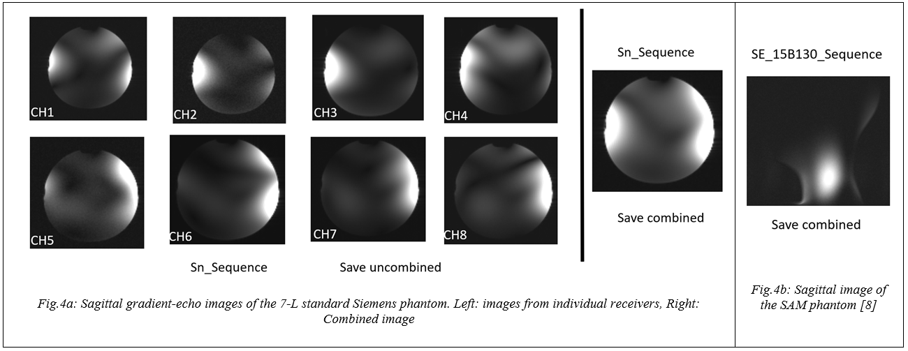
The reflection coefficient (S11) for all channels at 297.2 MHz was lower than -18 dB and the transmission (S21) between any two channels was lower than -10 dB. The quality-factor ratio (unloaded/loaded) for all channels was better than 1.96. Figure 4a shows gradient-echo images of the standard 7-L Siemens phantom (per 1000g H2O dist: 3,75g NisO4 x 6 H2O + 5g NaCl) as acquired from individual receivers and when combined. Fig 4b shows the save combined mode (SE_15B130 sequence) using SAM phantom [8].
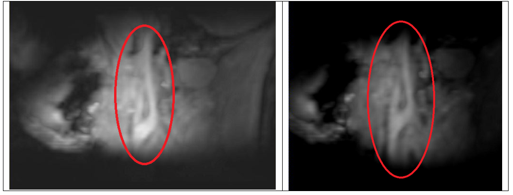
Finally, in vivo imaging of the carotid was performed on a healthy volunteer. Fig. 5 presents the preliminary in vivo results (GRE sequence, sequence variant: fl3d1). It must be noted that these in vivo results are very preliminary results and next step is to optimize the phase and amplitude of each channel to achieve maximum B1+ homogeneity in both carotid arteries.
Conclusion
An 8-channel transceiver carotid coil was constructed and evaluated on a 7T Terra MRI system in pTx mode. The optimized coil array produced sufficient B1+ efficiency and SNR. The concept of two four-channel transmit/receive RF arrays, one for each side of the neck, with one RF shield per side, can be used for in vivo MR imaging of the carotid arteries at 7T in pTx mode.Acknowledgements
This project has been funded by the Canadian Institutes of Health Research (MOP-123492), the Canadian Foundation for Innovation (JELF 34874 and Innovation Fund 33397), Brain Canada in Partnership with Health Canada (PSG15-3755), and the Canada First Research Excellence Fund (HBHL-4b-CF-10). Research Support from Siemens Canada is also gratefully acknowledged.References
[1] O. Kraff, et al; A Transmit/Receive Radiofrequency Array for Imaging the Carotid Arteries at 7 Tesla, Investigative Radiology • Volume 46, Number 4, April 2011
[2] Eichfelder, G., & Gebhardt, M. Local specific absorption rate control for parallel transmission by virtual observation points. Magn. Reson. Med., 66(5), 1468–76
[3] Gilbert KM, et al; Radiofrequency coil for routine ultra-high-field imaging with an unobstructed visual field, NMR Biomed. 2020. Doj: 10.112/nbm.4457
[4] V. P. R Aluquin, et al; Magnetic resonance imaging in the diagnosis and follow up of Takayasu’s arteritis in children, Ann Rheum Dis 2002;61:526–529
[5] Hayes CE, Mathis CM, Yuan C. Surface coil phased arrays for high resolution imaging of the carotid arteries. J Magn Reson Imaging. 1996;6: 109–112
[6] CST studio suite 2017 (CST, Darmstadt, Germany)
[7] https://www.wantcominc.com/
[8] Speag.
swiss/components/phantoms/customized-2/sam-v4-2
Figures