3318
Target specific optimization of the transmit k-space trajectory stack-of-spirals and SPINS for pTx pulse design1High-field Magnetic Resonance, Max-Planck-Institute for biological Cybernetics, Tübingen, Germany, 2Biomedical Magnetic Resonance, University Hospital Tübingen, Tübingen, Germany, 3Advanced Imaging Research Center, University of Texas Southwestern Medical Center, Dallas, TX, United States
Synopsis
Four basis transmit k-space trajectories (a single variable density spiral-in, a two stack of variable density spiral-in, a three stack of variable density spiral-in and a SPINS trajectory) were optimized for pTx radiofrequency pulse design in order to match the excitation target pattern. The parameter to be optimized where the parameter of the analytical equations of the basis trajectories. The procedure was tested on local excitation and whole brain-like excitation target patterns. Optimized trajectories enabled considerably improved radiofrequency pulse performance, compared to radiofrequency pulses based on unsuited trajectories. The optimization code is available online as open source (https://github.com/ole1965/workflow_OTUP.git).
Introduction
The parallel transmission (pTx) technique1,2 is the most promising approach to overcome the inhomogeneity issue of the radiofrequency (RF) field, typical for ultra high field.Usually a pTx RF pulse is calculated based on a pre-defined transmit k-space trajectory. For a desired target excitation pattern ‘the choice of a suitable transmit k-space trajectory is crucial’3.
In this work, we investigated and optimized four basis transmit trajectories (a single variable density spiral-in4,5,6 (1SOS), a two stack of variable density spiral-in7,8 (2SOS), a three stack of variable density spiral-in (3SOS) and a SPINS9 trajectory) for pTx RF pulse design. The analytical equations of spirals4 and SPINS9 were considered in order to optimize the trajectories.
This approach is similar to the works from Davids et al.10 and Herrler et al.11. However, the former optimized the k-space trajectories by setting control points (instead of the analytical equations), while the latter only optimized SPINS for whole brain excitation.
Methods
A single variable density spiral-in trajectory4 can be represented by:\begin{equation}
k(t) = \lambda t^{\alpha}e^{i\omega t}
\end{equation}
with $$$t = 1,1-\frac{1}{T-1},1-\frac{2}{T-1},...,0$$$ is the time and additional parameters are $$$\lambda, \alpha$$$ and $$$\omega$$$.
For 1SOS the spiral equation was implemented in a cost-function having the equation parameter $$$T,\lambda,\alpha,\omega$$$ and the position $$$z$$$ of the spiral on the $$$k_z$$$-axis as input parameter. Within the cost-function, the spiral $$$k$$$ was created according to these input parameters.
For that trajectory $$$k$$$, a RF pulse was designed with the ‘Spatial domain method’12. The output parameter of the cost-function was the root mean square error (RMSE) between the flip angle (FA) profile of the designed pulse (Bloch simulated) and the target pattern.
For 2SOS and 3SOS the procedure was analogous with two and three spirals, respectively.
A SPINS trajectory9 can be created using
\begin{equation}
k_r(t)=\frac{k_{max}}{1+e^{\alpha(\frac{t}{T}-\beta)}}\\
k_{\theta}(t)=ut\\
k_{\varphi}(t)=vt
\end{equation}
where $$$k_r$$$ is the radial coordinate, $$$k_{\theta}$$$ and $$$k_{\varphi}$$$ are the polar and azimuthal angles and $$$t = 1,...,T$$$ is the time. Additional parameters are $$$k_{max},\alpha,\beta,u$$$ and $$$v$$$.
Similar to 1SOS, 2SOS and 3SOS a cost-function with the SPINS parameter $$$k_{max},\alpha,\beta,u,v$$$ and $$$T$$$ as input parameter was implemented in order to create a SPINS trajectory for each set of parameters and to design a pulse based on this trajectory.
Each basis k-space trajectory was optimized separately with the ‘Particle swarm optimization’13, implemented in Matlabs particleswarm function. The particleswarm function was executed 20 times for each cost-function. From the 20 optimized parameter sets, the one that provided the lowest RMSE was set as the optimum. The maximum allowed trajectory duration was 10ms.
The RF pulse design was based on $$$B_0/B_1^+$$$ maps14 from one human subject measured in advance on a 9.4T whole-body MR scanner (‘Magnetom 9.4T’, Siemens Healthcare, Erlangen, Germany). The utilized in-house-built 16 channel coil15 consisted of eight transceiver loops.
The optimization procedure was tested on two local excitation and one whole brain-like excitation target pattern (Figure 1). The optimized trajectories were tested in simulations and in vivo.
Results
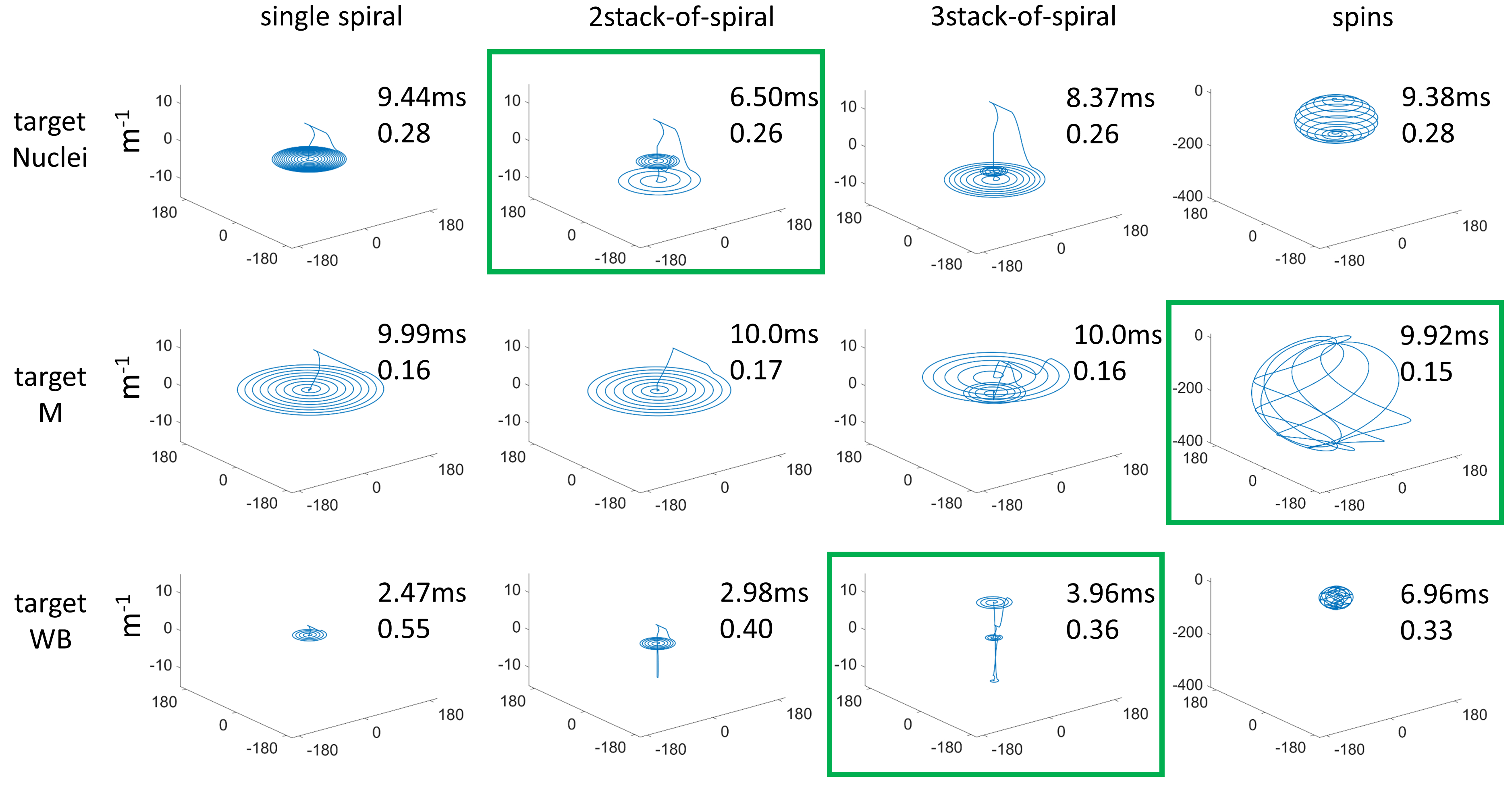
Figure 2 shows the optimized transmit k-space trajectories.For targetNuclei all four optimized trajectories provided RF pulses with similar RMSEs, however, the 2SOS result offered the shortest duration (6.50ms). The trajectories for targetM extended further into the outer k-space compared to the targetNuclei trajectories. All targetM results provided similar pulse durations and RMSEs. For targetWB all trajectories exhibited a drastically lower extend in k-space compared to the targetNuclei and targetM trajectories. The 3SOS result constituted the best compromise between duration (3.96ms) and RMSE (0.36) for targetWB.
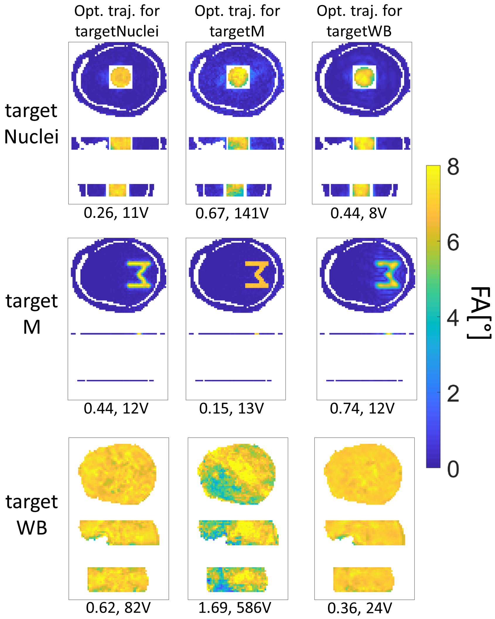
As Figure 3 shows, for each target the associated optimal transmit trajectory enabled the best performing RF pulse. If the underlying trajectory was not optimized for the respective target, the RF pulse performance diminished.
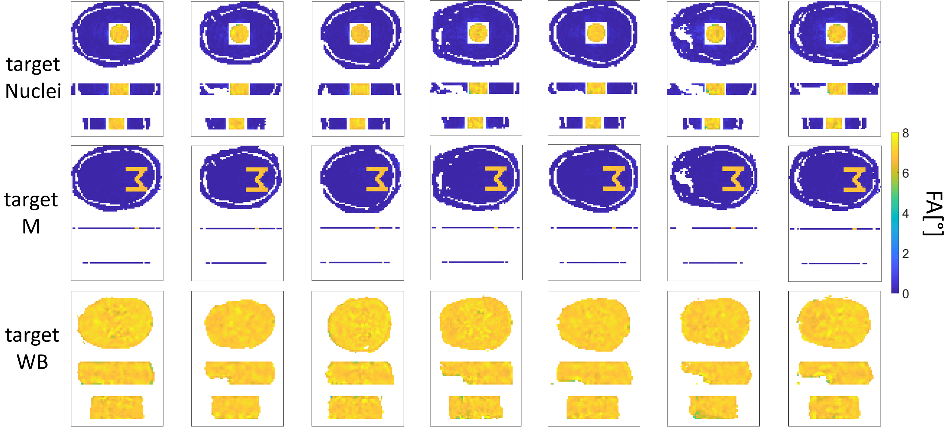
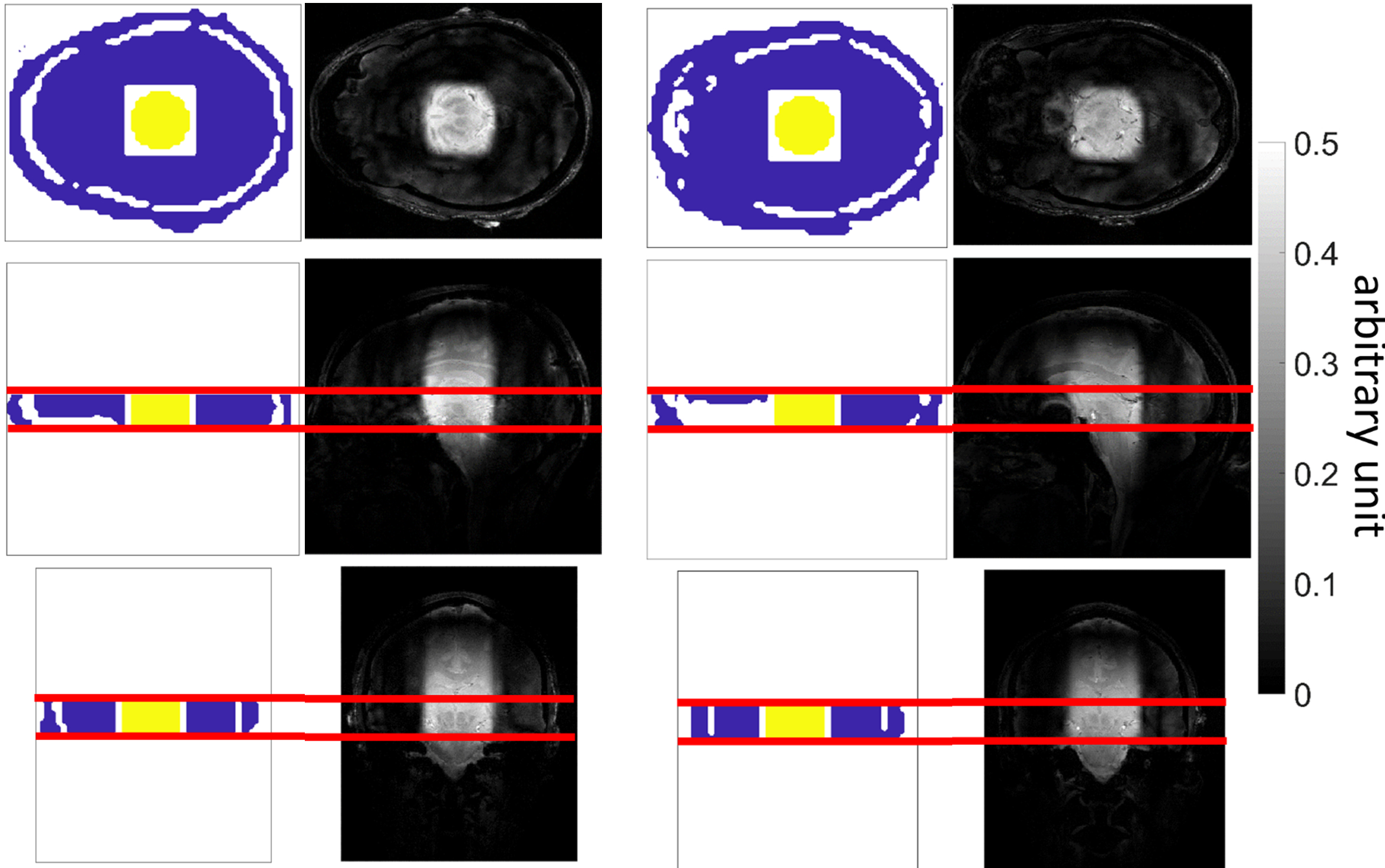
For each target the optimized trajectory produced (together with the RF pulses) excellent FA profiles (Figure 4). The in vivo results for targetNuclei showed local excitation of the central region of the human brain at 9.4T (Figure 5).
Discussion
Figure 3 verified that the utilization of an optimized trajectory was crucial for the RF pulse performance. If the RF pulse design for a certain target was based on a corresponding optimized transmit k-space trajectory the pulse performance was better compared to a non-corresponding underlying trajectory. Unsuited trajectories diminished the pulse performance.The optimized k-space trajectories revealed that with increasing complexity of the target excitation pattern the extent of the optimized trajectories in $$$k_x$$$ and $$$k_y$$$ direction in k-space increased. For the least complex targetWB the optimized trajectory ran close to the k-space center, covering only low frequencies. For that reason, the targetWB trajectory is unsuitable for excitation of targetM and vice versa (Figure 3).
The proposed transmit trajectory optimization method can be applied on the $$$B_0/B_1^+$$$ maps of one subject. The optimized trajectory can then be used for RF pulse design on any other subject (Figure 4 and 5). By means of an optimized transmit trajectory the RF pulse performances of universal pulses16,17 can be improved most likely.
Conclusion
We introduced and validated a new pTx pulse design method that optimizes the transmit k-space trajectory (stack of spiral and SPINS) to best match the excitation target of interest. The workflow code is available online as open source (https://github.com/ole1965/workflow_OTUP.git).Acknowledgements
Funding by the ERC Starting Grant (SYNAPLAST MR, Grant Number: 679927) of the European Union and the Cancer Prevention and Research Institute of Texas (CPRIT, Grant Number: RR180056) is gratefully acknowledged.References
1. Katscher U, Börnert P, Leussler C, van den Brink JS. Transmit SENSE. Magnetic Resonance in Medicine. 2002 Dec; 49: 144–150.
2. Zhu Y. Parallel excitation with an array of transmit coils. Magnetic Resonance in Medicine. 2004; 51: 775–784.
3. Schneider JT, Kalayciyan R, Haas M, Herrmann SR, Ruhm W, Hennig J, et al. Inner-volume imaging in vivo using three-dimensional parallel spatially selective excitation. Magnetic Resonance in Medicine. 2012 Jun; 69: 1367–1378.
4. Kim Dh, Adalsteinsson E, Spielman DM. Simple analytic variable density spiral design. Magnetic Resonance in Medicine. 2003 Jun; 50: 214–219.
5. Schröder C, Börnert P, Aldefeld B. Spatial excitation using variable-density spiral trajectories. Journal of Magnetic Resonance Imaging. 2003 Jun; 18: 136–141.
6. Liu Y, Feng K, McDougall MP, Wright SM, Ji J. Reducing SAR in parallel excitation using variable-density spirals: a simulation-based study. Magnetic Resonance Imaging. 2008 Oct; 26: 1122–1132.
7. Irarrazabal P, Nishimura DG. Fast Three Dimensional Magnetic Resonance Imaging. Magnetic Resonance in Medicine. 1995 May; 33: 656–662.
8. Shao T, Xia L, Tao G, Chi J, Liu F, Crozier S. Advanced Three-Dimensional Tailored RF Pulse Design in Volume Selective Parallel Excitation. IEEE Transactions on Medical Imaging. 2012 May; 31: 997–1007.
9. Malik SJ, Keihaninejad S, Hammers A, Hajnal JV. Tailored excitation in 3D with spiral nonselective (SPINS) RF pulses. Magnetic Resonance in Medicine. 2011 Aug; 67: 1303–1315.
10. Davids M, Schad LR, Wald LL, Guérin B. Fast three-dimensional inner volume excitations using parallel transmission and optimized k-space trajectories. Magnetic Resonance in Medicine. 2015 Nov; 76: 1170–1182.
11. Herrler J, Liebig P, Gumbrecht R, Ritter D, Schmitter S, Maier A, et al. Fast online-customized (FOCUS) parallel transmission pulses: A combination of universal pulses and individual optimization. Magnetic Resonance in Medicine. 2021 Jan; 85: 3140–3153.
12. Grissom W, Yip Cy, Zhang Z, Stenger VA, Fessler JA, Noll DC. Spatial domain method for the design of RF pulses in multicoil parallel excitation. Magnetic Resonance in Medicine. 2006; 56: 620-629.
13. Kennedy J, Eberhart R. Particle swarm optimization. In Proceedings of the IEEE International Conference on Neural Networks, Perth, Australia, 1995, #1942-1945.
14. Bosch D, Bause J, Ehses P, Zaiss M, Scheffler K. Rapid pre-saturated TFL transmit field mapping with an optimized 3D centric single-shot readout. In Proceedings of the International Society for Magnetic Resonance in Medicine Meeting 2020 (Virtual Conference), 3703.
15. Avdievich NI, Giapitzakis IA, Pfrommer A, Borbath T, Henning A. Combination of surface and `vertical' loop elements improves receive performance of a human head transceiver array at 9.4 T. NMR in Biomedicine. 2017 Dec; 31: e3878.
16. Gras V, Vignaud A, Amadon A, Bihan DL, Boulant N. Universal pulses: A new concept for calibration-free parallel transmission. Magnetic Resonance in Medicine. 2016 Feb; 77: 635-643.
17. Geldschläger O, Bosch D, Glaser S, Henning A. Local excitation universal parallel transmit pulses at 9.4T. Magnetic Resonance in Medicine. 2021 Jun.
18. Cloos MA, Boulant N, Luong M, Ferrand G, Giacomini E, Bihan DL, et al. kT-points: Short three-dimensional tailored RF pulses for flip-angle homogenization over an extended volume. Magnetic Resonance in Medicine. 2011 May; 67: 72–80.
19. Gras V, Luong M, Amadona A, Boulant N. Joint design of kT-points trajectories and RF pulses under explicit SAR and power constraints in the large flip angle regime. Journal of Magnetic Resonance. 2015 Dec; 261: 181-189.
20. Zelinski AC, Wald LL, Setsompop K, Goyal VK, Adalsteinsson E. Sparsity-Enforced Slice-Selective MRI RF Excitation Pulse Design. IEEE Transactions on Medical Imaging. 2008 Sep; 27: 1213–1229.
21. Grissom WA, Khalighi MM, Sacolick LI, Rutt BK, Vogel MW. Small-tip-angle spokes pulse design using interleaved greedy and local optimization methods. Magnetic Resonance in Medicine. 2012 Mar; 68: 1553–1562.
Figures