3315
Optimization of the Double-Row 16-channel Transmit-only RF Array Coil for Human Brain Imaging at 9.4T.1Department of Biomedical Magnetic Resonance, Eberhard Karls University Tübingen, Tübingen, Germany, 2Magnetic Resonance Center, Max Planck Institute for Biological Cybernetics, Tübingen, Germany
Synopsis
At 9.4T, transmit-only RF array coils for human brain imaging provide mediocre transmit efficiency due to a weak loading factor, which implies low power dissipation in the tissues. In this work we aim to optimize using the full-wave simulations a dual row 16-channel transmit-only array to improve the transmit performance. For that purpose, we simulated eight different array designs containing the loops with overlapping and gaps between the rows and two configurations of loopoles. We have shown that the optimized design with the overlapped loops provides improvement ~15% in Tx-efficiency and 16.5% improvement in SAR-efficiency compared to the reference coil.
Purpose
To improve transmit (Tx) performance of the Tx-only 16-channel dual-row RF array coil for human brain imaging at 9.4T.Introduction
We aim to optimize the entire 16-Tx/32-Rx RF array coil design. At first, we optimized the design of the 16-loop Tx-only array coil. Unlike transceiver coils [1], Tx-only coils are much larger in diameter to reserve some space for Rx-arrays [2]. Consequently, placement of Tx-elements far from the human tissue drastically reduces the loading factor (power absorbed in the tissues) and Tx-performance [2]. High Tx-performance of the coil is crucial due to the RF power limited to 8kW in the single channel Tx-mode. In addition, considering losses in cables and the coil interface, final power absorbed by the tissues could be only ~30% of the total power. To increase the loading factor, we proposed to test several designs. Firstly, we increased the length of the loops in Z-direction, while keeping the total coil’s length. To increase the loops length, we introduced overlapping between the rows [3]. This also simplifies the coil design by reducing the number of decoupling transformers. Secondly, by extending the loops above the superior part of the head, the Tx-efficiency can be improved in this location [4]. Thirdly, we tested new concept of the loopoles [5] that could potentially provide a gain in the Tx-performance.Methods
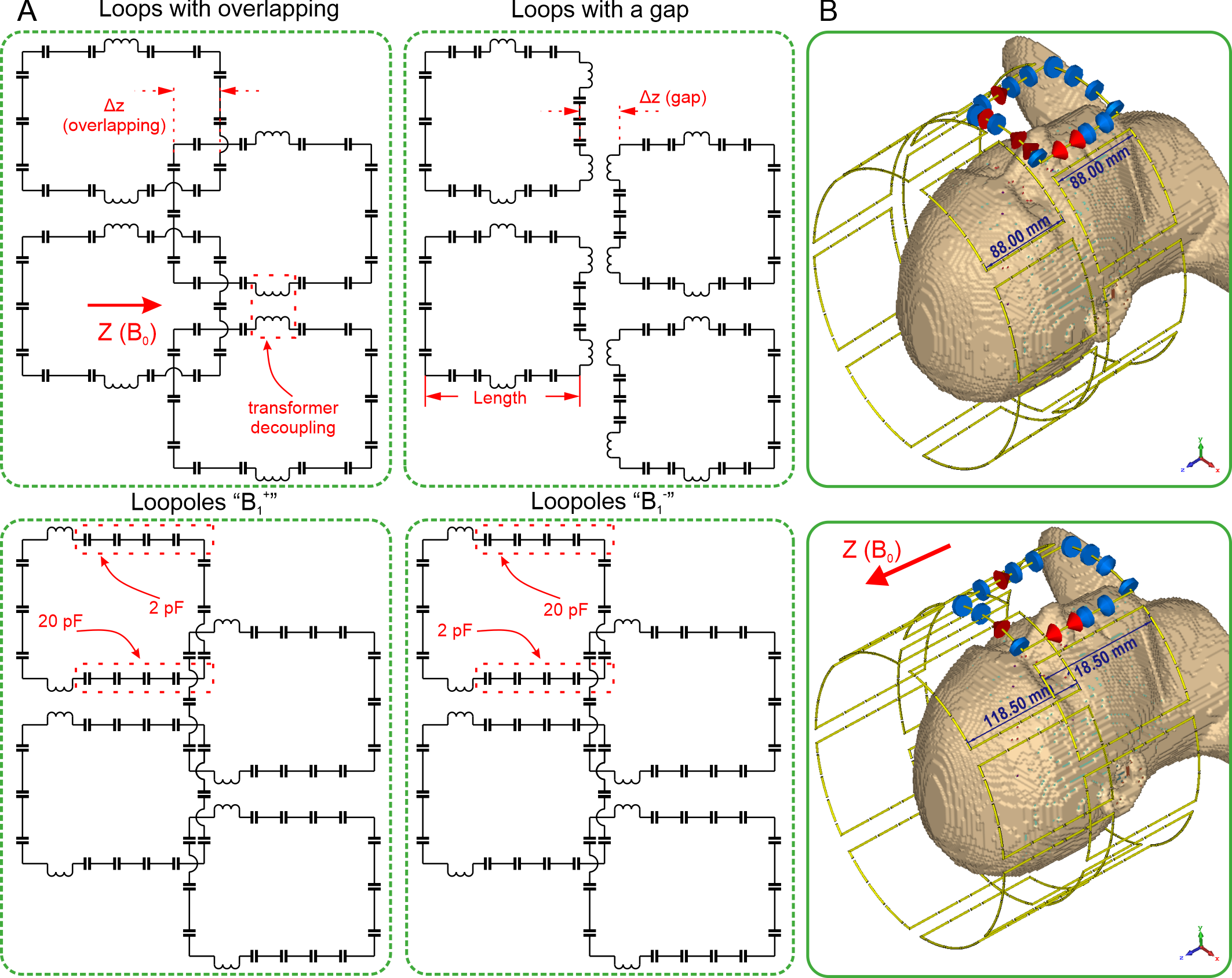
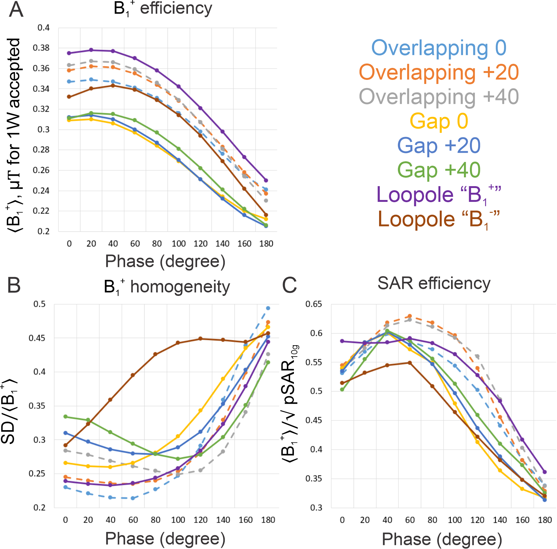
To confirm our hypothesis, we conducted full-wave simulations of eight Tx-only array setups using the Time-Domain Solver of the commercial CST Studio Suite 2021 software. All coils were loaded by the Duke voxel model. We split these setups into three groups. First group has the loops with overlapping between the rows, and gaps within the rows. Second group contains the loops with gaps both between and within the rows. All gaped loops have transformer decoupling. Third group contains extended by 20mm loopole coils optimized for transmit (“B1+”) and for receive (“B1-”) modes. Fig. 1 shows the sketches of these designs. As a reference coil, we used the array coil with the 14mm gap between the rows, the total length of 190mm, and an elliptical cross section of 243mm x 281.5mm. The loop size was 88mm x 88mm. Then, each coil was extended by 20 and 40mm above the superior part of the head while retaining its position close to the shoulder. In each configuration we adjusted the transformer decoupling and overlapping between the rows for both the loops and loopoles. Each array coil was driven in the circular polarized (CP) mode. In addition, we varied the phase shift from 0° to 180° between the rows (Fig. 2). The optimal phase shift in terms of maximum peak-SAR efficiency (‹B1+›/√pSAR10g) was chosen for each coil. Then, we assessed Tx-efficiency (‹B1+›/√P) and homogeneity of Tx-field (SD/‹B1+›), and chose the optimal design.Results and Discussion
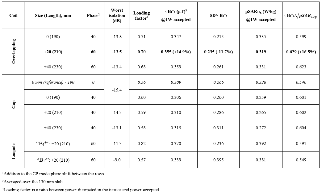
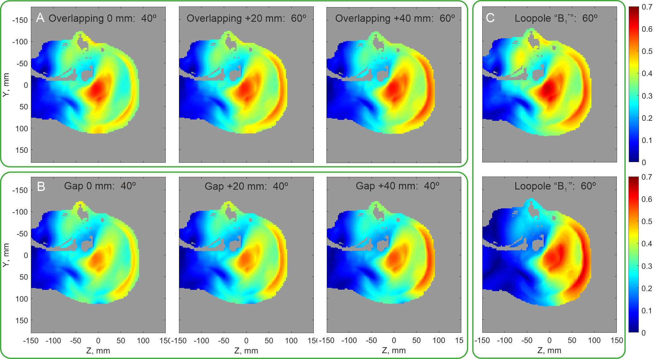
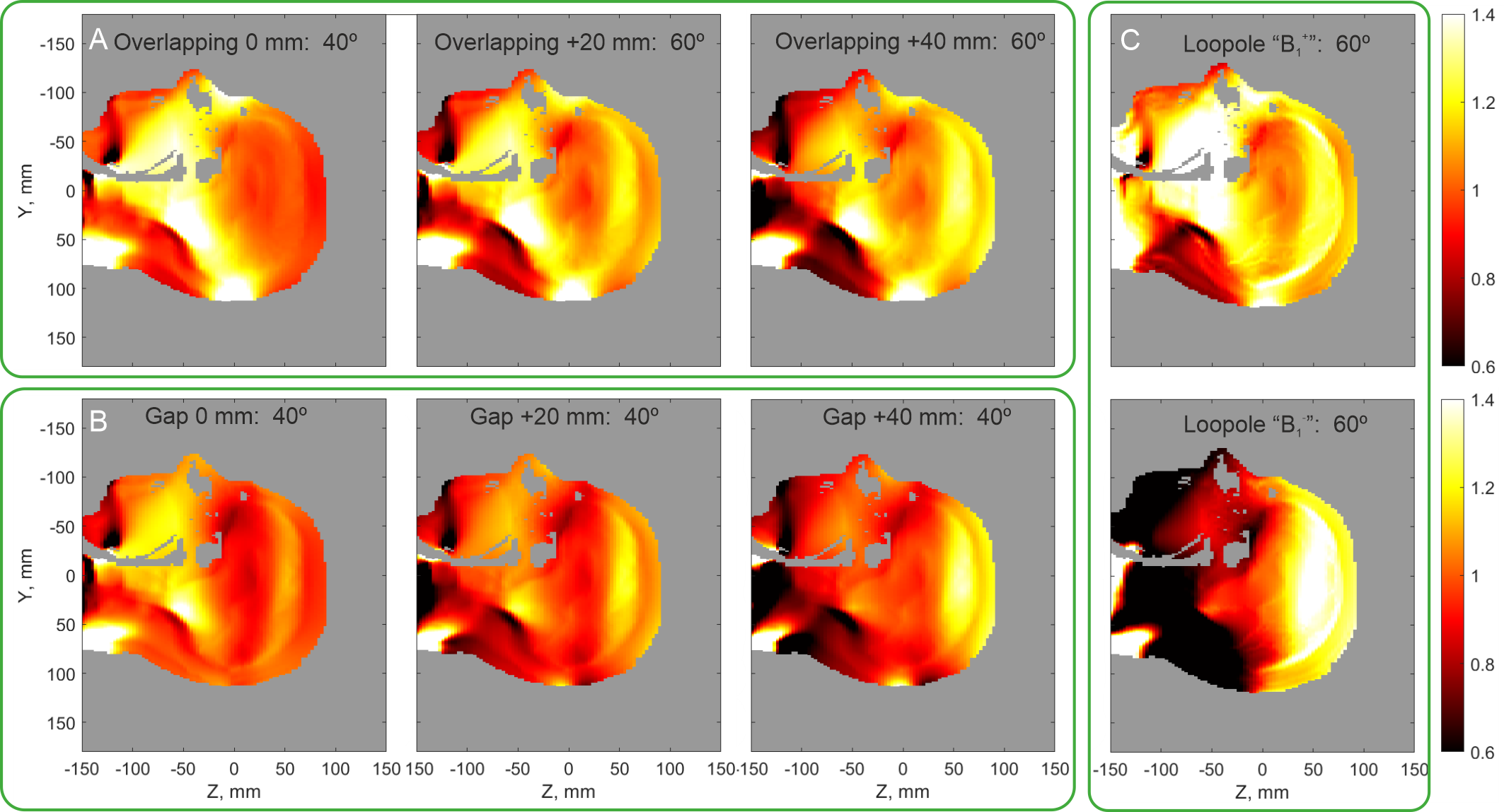
For the gaped design the worst-case isolation between two loops was -13.1dB. In case of overlapped design, the worst isolation was -13.4dB. For the loopoles we achieved the isolation of -11.3 and -9 dB for “B1+” and “B1-” configurations, respectively (Fig. 3). Fig.2 shows the dependences of coil performances on the phase shift between the rows. The overall Tx-performance assessment for the optimal configuration is shown in Fig.3. Fig.4 presents the B1+ maps in the central sagittal cross-section obtained with optimal phase shifts. Finally, Fig.5 shows the ratio of B1+ to the B1+ of the reference coil. As seen in Figs. 2 and 3, the reference coil Tx-performance can be improved by 10% with an additional phase shift between the rows. While extending the reference coil in the Z-direction provides a gain in SAR-efficiency (~11.5%), the homogeneity drops by 10% and 16.7% for 20mm and 40mm extensions, respectively. Furthermore, the loopoles optimized for the Tx-mode demonstrate improvement of 9.4% compared to the reference coil driven in CP mode in terms of SAR-efficiency and 12.7% in terms of field homogeneity. In contrast, the loopoles optimized for the receive mode shows the worst results. Then, the coil of the initial size but with overlapping demonstrates 10.9% gain in SAR-efficiency and 20.9% improvement of homogeneity compared to the reference coil. However, the coil with overlapping and 20mm extension demonstrates best results in terms of SAR-efficiency. Compared to the reference coil, coil with overlapping and 20mm extension provides 16.5% gain in SAR-efficiency and 11.7% homogeneity improvement. Further enlarging the coil length shows comparable SAR-efficiency gain and drop of homogeneity compared to the new optimal design. Moreover, as it was expected, enlarging coil in the Z-directions improves Tx-performance in the superior brain part (Fig. 4C). Finally, the new optimal design improves the loading factor from 56% for the reference coil to 70%, which results in ~15% improvement in Tx-efficiency.Conclusion
We simulated and evaluated the new 16-channel Tx-only coil for brain imaging at 9.4T. The new design was optimized compared to the reference coil in terms of field homogeneity and SAR-efficiency. The optimal design provided an improvement of the field homogeneity by 11.7%, ~15% in Tx-efficiency, and gain in SAR-performance by 16.5%. At the moment we are assembling the prototype of the new 16-Tx/32-Rx array coil for brain imaging ay 9.4T.Acknowledgements
Financial support of the Max-Planck-Society, ERC Advanced Grant “SpreadMRI”, No 834940 and DFG Grant SCHE 658/12 is gratefully acknowledged.References
[1] N. I. Avdievich, I. A. Giapitzakis, J. Bause, G. Shajan, K. Scheffler, and A. Henning, “Double-row 18-loop transceive–32-loop receive tight-fit array provides for whole-brain coverage, high transmit performance, and SNR improvement near the brain center at 9.4T,” Magn. Reson. Med., vol. 81, no. 5, pp. 3392–3405, May 2019, doi: 10.1002/mrm.27602.
[2] G. Shajan, M. Kozlov, J. Hoffmann, R. Turner, K. Scheffler, and R. Pohmann, “A 16-channel dual-row transmit array in combination with a 31-element receive array for human brain imaging at 9.4 T,” Magn. Reson. Med., vol. 71, no. 2, pp. 870–879, 2014, doi: 10.1002/mrm.24726.
[3] N. I. Avdievich, I. A. Giapitzakis, A. Pfrommer, and A. Henning, “Decoupling of a tight-fit transceiver phased array for human brain imaging at 9.4T: Loop overlapping rediscovered,” Magn. Reson. Med., vol. 79, no. 2, pp. 1200–1211, Feb. 2018, doi: 10.1002/MRM.26754.
[4] N. I. Avdievich, G. Solomakha, L. Ruhm, A. V. Nikulin, A. W. Magill, and K. Scheffler, “Folded-end dipole transceiver array for human whole-brain imaging at 7 T,” NMR Biomed., vol. 34, no. 8, Aug. 2021, doi: 10.1002/NBM.4541.
[5] K. Lakshmanan, M. Cloos, R. Brown, R. Lattanzi, D. K. Sodickson, and G. C. Wiggins, “The ‘Loopole’ Antenna: A Hybrid Coil Combining Loop and Electric Dipole Properties for Ultra-High-Field MRI,” Concepts Magn. Reson. Part B, Magn. Reson. Eng., vol. 2020, pp. 1–9, Sep. 2020, doi: 10.1155/2020/8886543.
Figures