3314
iDREAM: T1-bias compensated DREAM B1+ mapping using adiabatic inversion pulses
Kay Nehrke1 and Peter Börnert1
1Philips Research Laboratories, Hamburg, Germany
1Philips Research Laboratories, Hamburg, Germany
Synopsis
A refinement of the DREAM B1+ mapping technique is presented, that removes the potential T1-bias from the B1+ maps. It is based on a phase cycling scheme including adiabatic inversion pulses and improves the B1+ mapping accuracy and reliability and extends the dynamic working range of the DREAM approach. The method has been successfully validated on phantoms and in vivo on the brain at 3T.
Introduction
At higher field strength, fast and accurate B1+-mapping is an essential prerequisite for many applications as e.g. parallel transmit MRI or quantitative methods like MR fingerprinting. The DREAM approach (Dual Refocusing Echo Acquisition Method, (1)) allows volumetric B1+ mapping, covering the whole transmit coil volume in a few seconds, which is more than ten times faster than other B1+ mapping approaches. However, DREAM is based on a STEAM-preparation module, and requires short shot durations to avoid T1-related signal recovery artefacts. Moreover, short T1 reduces the accurate working range of the method. Hence, a careful trim of the sequence parameters is required (1), or an appropriate filtering of the FID signal has to be performed in reconstruction (2). In this work, a T1-compensated phase-cycling scheme based on adiabatic RF inversion pulses, dubbed iDREAM, is presented, which removes the T1-sensitivity of the DREAM approach completely. iDREAM B1+ mapping was performed on phantoms and in vivo on the brain at 3T to study the performance of this new approach.Methods
A DREAM phase cycling scheme has been implemented, where signals from two averages, acquired with or without adiabatic inversion pulse, respectively (Figure 1), were subtracted by switching the phase of the RF imaging pulse between 0 and 180 degrees for the two averages. Alternatively, one could also toggle the receiver phase. These measures eliminate the potential T1 bias in DREAM (Figure 2). An adiabatic inversion pulse was chosen to account for a broad range of Tx sensitivities (pulse angle = 750 deg). B1+-mapping experiments were performed on phantoms (bottle filled with mineral oil) and in vivo (brain) on a 3T MRI system. A DREAM protocol with a long acquisition train was chosen on purpose to increase T1 sensitivity (scan matrix = 120x90, pixel size = 2.5mm, slice thickness = 7mm, TR = 7.6ms, acq. train duration = 660 ms). A shot delay of 5s was used to allow full T1 recovery. For the phantom experiments, single-slice T1-compensated DREAM B1+ maps were acquired for nominal STEAM flip angles between 5 and 90 degrees in steps of 5 degrees. A 10x10 pixel ROI in the centre of the phantom was used to average STE and FID signals, and to derive the STEAM angle according to Eq.4. The flip angles derived by DREAM were plotted against the nominal angles, which were regarded as accurate reference for an oil bottle at 1.5T. The experiments and the analysis were repeated for conventional DREAM without inversion pulse for comparison. For the in-vivo experiments, a transversal slice through the brain (intersecting the ventricle) was chosen and DREAM B1+ maps with and without T1 compensation were acquired. In addition, also combined T1- and T2-compensation was applied by using the virtual stimulated echo (3) in combination with inversion pulse cycling.Results
The experimental results on the oil phantom show, that the standard DREAM B1+ map starts to degrade above 50 degrees (Figure 3). This is due to the short T1 of the oil (about 100ms) and the long acquisition duration of the high-resolution DREAM protocol, which was deliberately chosen to emphasize the T1 bias. In contrast, the (T1-compensated) iDREAM B1+ maps are accurate up to 85 degrees. Thus, the iDREAM sequence covers a much larger portion of the theoretical working range than the standard DREAM sequence without a bias. In vivo, without T1 compensation, a strong T1 contrast between ventricle, grey and white matter and the rim of the head is visible. In case of T1 compensation, the contrast between rim, grey and white matter disappears, and only slight contrast of the ventricle remains. This tiny remaining contrast disappears in case of both T1 and T2 compensation, yielding a perfectly smooth B1+ map (Figure 4). The profile plots show that the T1 bias of standard DREAM results in an underestimation of B1+ up to 5% in grey and white matter. Note that this T1 bias was emphasized by the elongated shot duration.Discussion
The proposed refinement makes the DREAM sequence more accurate, robust, and versatile. The acquisition train duration can be prolonged without performance degradation. Hence, also larger scan matrices may still be acquired in a single shot. Moreover, other view orders than centric, like linear, may be used if appropriate. Compared to advanced filtering performed in reconstruction (2), the DREAM Equation (Eq.4) preserves its simple analytical form. However, as a drawback, acquisition time is doubled. Nevertheless, due to the high speed of the DREAM acquisition, this is acceptable for many applications, especially for quantitative MRI applications, where a better accuracy and a gain in SNR of the B1+ maps are appreciated.Acknowledgements
No acknowledgement found.References
1. Nehrke K. and Börnert P., Magn Reson Med 68:1517-26 (2012).
2. Ehses P. et al. Magn Reson Med 82:924-934 (2019).
3. Nehrke K. et al. Magn Reson Med 71:246–256 (2014).
Figures
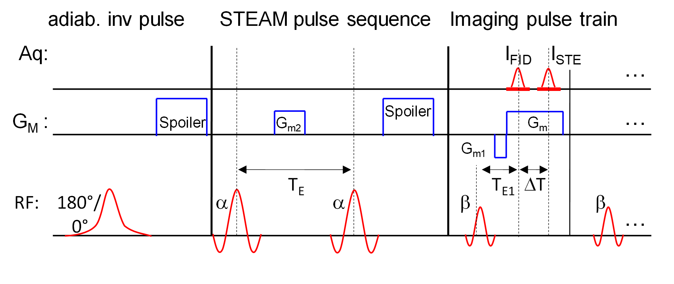
FIG. 1.: T1-compensated DREAM pulse sequence
scheme, consisting of adiabatic RF
inversion pulse (left), STEAM magnetization preparation (center) and TFE-like low-angle
single shot imaging sequence (right, first module is shown).

FIG. 2: Equations for DREAM signal equations. The derivation shows that the T1 bias (E1 term) is completely eliminated in the final DREAM equation.
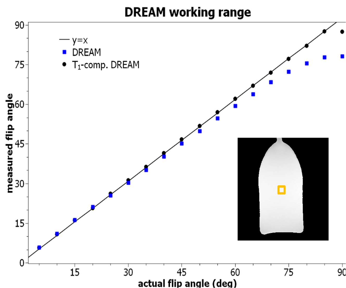
FIG. 3. Accuracy of DREAM B1+ maps. The flip angle
derived from DREAM in a phantom scan (bottle of mineral oil) is plotted against the actual flip angle for the DREAM
working range between 0 and 90 degrees for normal DREAM (blue symbols) and T1-bias compensated DREAM (black symbols). The orange box indicates the image ROI used for the analysis. Note the extended working range for the T1-bias compensated DREAM.
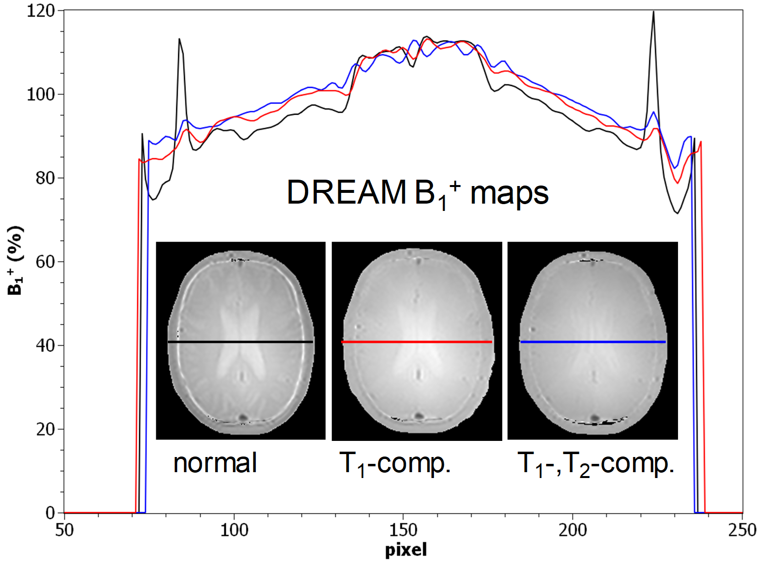
FIG. 4: DREAM B1+ maps of brain, acquired without compensation (left),
with T1- (center) and both T1-,T2- bias compensation (right) are shown along with
profile plots through the ventricle (black: without, red: with T1-, blue with
T1-, T2-bias compensation). Note the vanishing contrast shine through.
DOI: https://doi.org/10.58530/2022/3314