3310
A Dedicated Transceiver 8Tx/16Rx pTx Coil Array for Ex-vivo MRI Histology of Post-infarction Myocardium on a Whole-body 7T Scanner1Chair of Molecular and Cellular Imaging, Comprehensive Heart Failure Center (CHFC), University Hospital Wuerzburg, Wuerzburg, Germany
Synopsis
The purpose of this work was to develop and investigate a dedicated transceiver 16-element antisymmetric loop array for high-resolution imaging of the ex-vivo porcine heart at 7T. The array was interfaced to a 7T scanner in parallel transmit (pTx) mode (8Tx/16Rx). Electromagnetic-field (EMF) simulations were performed with the antisymmetric array loaded with a spherical phantom and a human heart (Billie). The optimization of the B1+-shimming for both sTx and pTx applications was performed using simulated and experimental B1-maps. The array was successfully tested to acquire ultra-high resolution (0.1x0.1x0.8mm voxel) images of the post-infarction scar tissue in the excised pig heart.
Introduction
A wide variety of different coil array designs have allowed significant progress for body imaging at ultrahigh-field (UHF) strengths ($$${B_0}$$$≥7T) (e.g., using local Tx/Rx loop1-4 and dipole antenna arrays5,6). Significant advancement of both $$${B_1^+}$$$-shimming and parallel imaging capabilities was demonstrated for in-vivo cardiac MRI (cMRI) in pigs using an antisymmetric 8Tx/16Rx loop array7. MRI-measurements of hearts ex-vivo at UHF can provide high resolution and high fidelity ground truth data that complements in-vivo cMRI with image quality not compromised by physiologic or intentional motion. Moreover, scan times can be significantly longer than in animals or humans in-vivo. In extreme cases scanning can be performed over many hours and, thus, image quality and spatial resolution can approach new dimensions in the assessment of static tissue properties like microstructure or tissue susceptibility effects. For the highest SNR and spatial resolution, the optimal Tx and Rx hardware coil design is a crucial factor. In this study, we describe the design, simulation, implementation, and testing of a custom-built, 8Tx/16Rx array dedicated to high-resolution imaging of ex-vivo hearts. The array was successfully tested to acquire ultra-high resolution (0.1x0.1x0.8mm voxel) of the post-infarction scar tissue in the excised pig heart.Methods
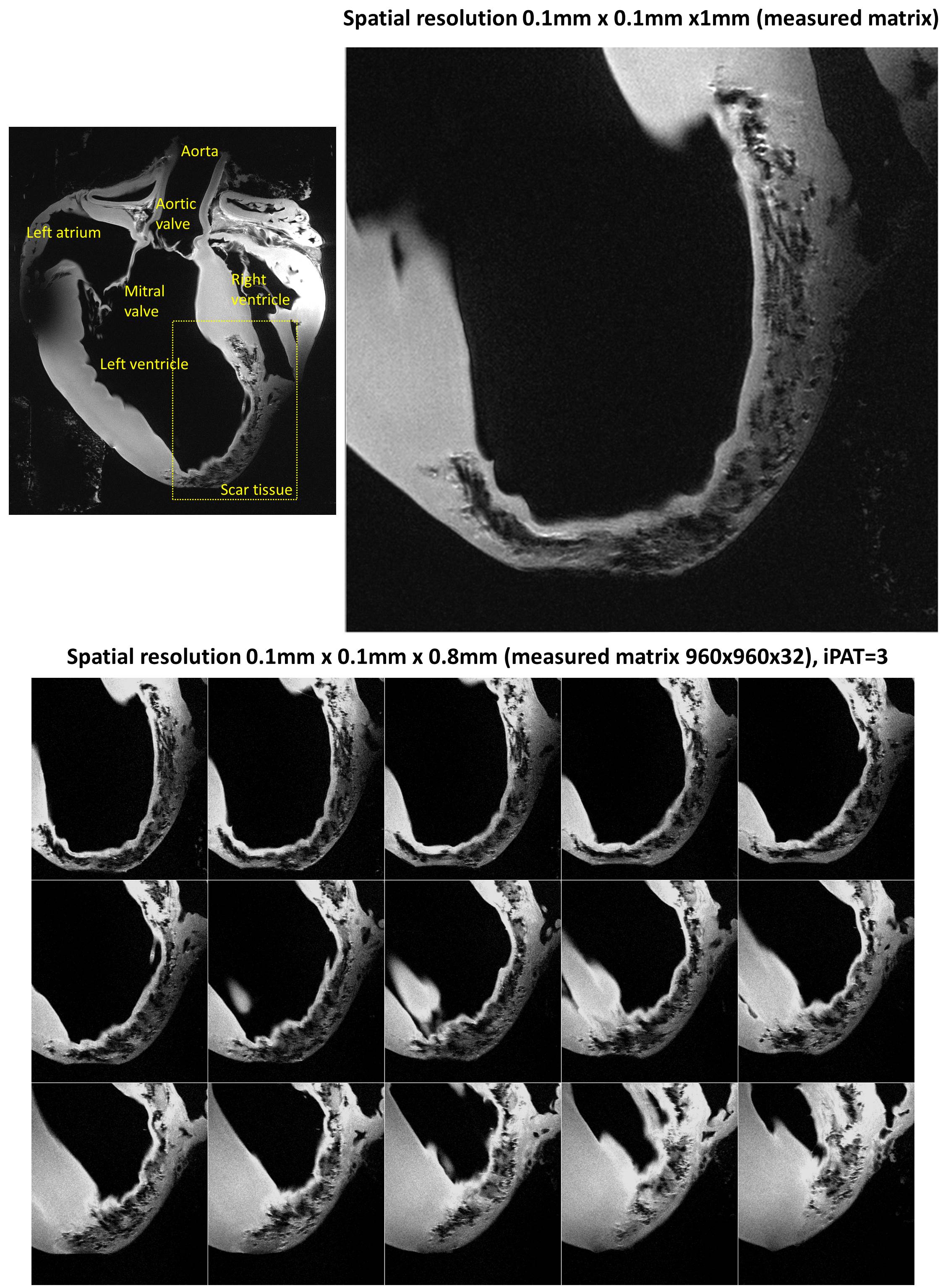
The 16-elements of the dedicated coil array were designed to bend around an elliptical-shape housing with major/minor axes of 12.3/10.7cm. The Cu trace width is 4mm etched on a 0.3mm FR4 PCB-substrate. The array was split into two PCB sections to keep 5.4cm spacing on the housing for routing the RF-cables [Figure 1]. The top PCB part is composed of 10-loops (elements 1-10) and the bottom part is composed of 6-loops (elements 11-16). The sizes of elements 1, 2, 7, 8, 9, 10, 11, and 12 were 2.3×5.8cm2. The decoupling between elements 1, 2, 7, and 9 was accomplished using a common conductor and shared decoupling capacitor (SDC) ($$${C_1^d}$$$ and $$${C_3^d}$$$). The other 8-elements were distributed around the central two loops in an antisymmetric distribution7. The size of elements 3, 4, 13, and 14 was 3.5×3.5cm2. Elements 3 and 4 were decoupled from elements 1 and 2 using SDC ($$${C_2^d}$$$). The size of elements 5, 6, 15, and 16 was 2.2×6.9cm2. Elements 5, 7, and 9 and the identical elements 6, 8, and 10 were decoupled from the neighboring elements using capacitive decoupling ($$${C_5^d}$$$, $$${C_6^d}$$$, $$${C_7^d}$$$, $$${C_8^d}$$$, and $$${C_9^d}$$$) with a decoupling gap of 9mm. The total external dimensions for the top and bottom PCB parts were 18.87×12.8cm2 and 10.9×12.8cm2, respectively. EM-simulations were performed using CST-Microwave-Studio when the array loaded with a 10cm spherical phantom (εr=59.3 and σ=0.79-S/m) and a voxel human heart model (Billie) (εr=69.4 and σ=0.90-S/m). All feeding ports, tuning, matching, and decoupling capacitors were modeled as 50-Ω discrete face ports. For matching, tuning, and decoupling, RF-circuit co-simulation was employed in CST-Design-Studio to get an initial guess for the optimal lumped elements8. To characterize the Tx performance of the array, $$$CoV=\frac{std(B_1^+)}{mean(B_1^+)}$$$ and $$$Tx_{eff}=\frac{mean(B_1^+)}{\sqrt{P_{acc}}}$$$ were computed. To form an 8Tx/16Rx array compatible with the pTx system, every two neighboring elements were combined in one Tx-channel. For example, $$${Tx_1}$$$ was formed by pairing the two elements 1 and 4 in one Tx-channel [Figure 1a]. The ex-vivo array was connected to a 16-channel interface with 16-Tx/Rx switches and 16-preamplifiers via 4-ODU plugs. All measurements were performed using a Magnetom™ “Terra” 7T scanner with an 8-channel pTx amplifier (Siemens, Erlangen, Germany). The array was tested with an excised pig heart with the measurement of relative $$${B_1}$$$-maps for offline pTx-shimming and g-factors with high parallel imaging acceleration factors. The testing ex-vivo measurements were performed using the excised heart of an 85-kg pig with infarction induced approximately 60-days before euthanasia. The pulse sequence used was turbo-spin-echo with echo train length=4, TE/TR=15/2000ms, acquisition matrix=960x810, slice thickness=1mm and 0.8mm, physical pixel size in-plane=0.1x0.1mm, number of averages=16. The heart was fixed by 4% formalin immediately after excision. For the measurements, the heart was placed in a container filled with Fomblin™ oil.Results
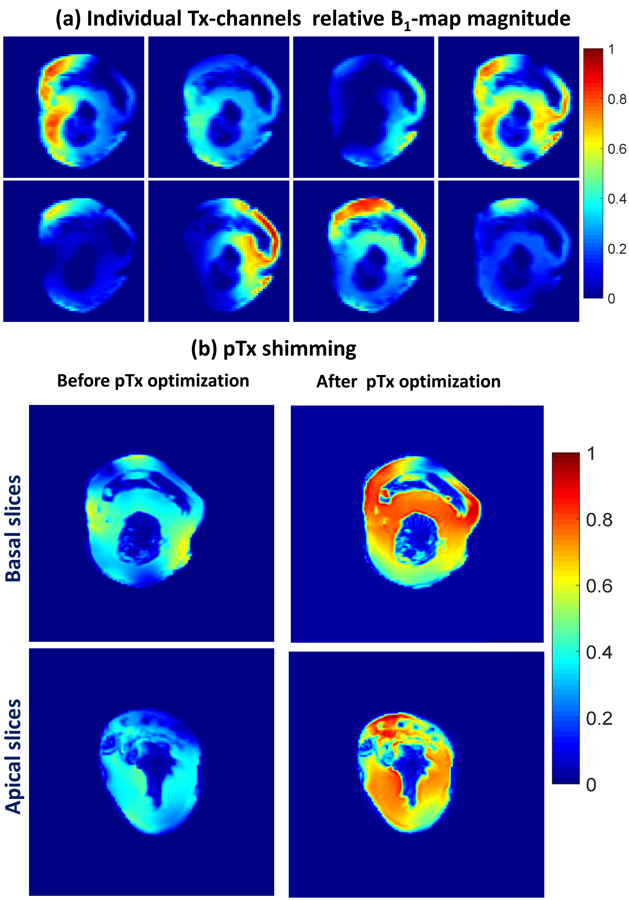
Figure 2 shows the measured S-parameters for the 16-element dedicated array versus frequency for the four ODU plugs when the array was loaded with a 10cm spherical phantom. Most of the elements were matched better than −14dB. Figure 3 demonstrates the simulated $$${B_1^+}$$$-field distribution in central transversal, sagittal, and coronal planes for the dedicated array after static phase-only $$${B_1^+}$$$-shimming loaded within a voxel human heart model (Billie). Figure 4 shows the relative $$${B_1}$$$-maps of individual 8Tx channels and results of the $$${B_1^+}$$$-shimming performed offline using an in-house designed Matlab Toolbox. Figure 5 demonstrates that the new array can be successfully used for the ultra-high resolution “MRI-histology” of the post-infarcted myocardial tissue. The in-plane physical resolution of 0.1mm/pixel allows a very high level of detalization of the scar tissue.Discussion
The antisymmetric array design allows for adequate decoupling of individual elements which provide an efficient combination of transmitting ($$${B_1^+}$$$-shimming) and receiving (SNR, g-factor of parallel imaging) characteristics of the array. Parallel imaging with an acceleration factor up to R=4 was possible while maintaining a mean g-factor of 1.13 within the pig heart.Conclusion
The dedicated 8Tx/16Rx array demonstrated high efficiency of both Tx and Rx properties for ultra-high resolution ex-vivo myocardial tissue characterization imaging at 7T.Acknowledgements
This project is funded by the Federal Ministry of Education and Research (BMBF), Grant/Award Number: 01EO1004 & 01EO1504.References
- Graessl A, Renz W, Hezel F, et al. Modular 32-channel transceiver coil array for cardiac MRI at 7.0T. Magn Reson Med. 2014;72(1):276-290.
- Dieringer MA, Renz W, Lindel T, et al. Design and application of a four-channel transmit/receive surface coil for functional cardiac imaging at 7T. J Magn Reson Imaging. 2011;33(3):736-741.
- Grassl A, Winter L, Thalhammer C, et al. Design, evaluation and application of an eight channel transmit/receive coil array for cardiac MRI at 7.0 T. Eur J Radiol. 2013;82(5):752-759.
- Thalhammer C, Renz W, Winter L, et al. Two-dimensional sixteen channel transmit/receive coil array for cardiac MRI at 7.0 T: design, evaluation, and application. J Magn Reson Imaging. 2012;36(4):847-857.
- Raaijmakers AJ, Ipek O, Klomp DW, et al. Design of a radiative surface coil array element at 7 T: the single-side adapted dipole antenna. Magn Reson Med. 2011;66(5):1488-1497.
- Raaijmakers AJ, Italiaander M, Voogt IJ, et al. The fractionated dipole antenna: A new antenna for body imaging at 7 Tesla. Magn Reson Med. 2016;75(3):1366-1374.
- Elabyad IA, Terekhov M, Lohr D, Stefanescu MR, Baltes S, Schreiber LM. A Novel Mono-surface Antisymmetric 8Tx/16Rx Coil Array for Parallel Transmit Cardiac MRI in Pigs at 7T. Scientific Reports. 2020;10(1):3117.
- Kozlov M, Turner R. Fast MRI coil analysis based on 3-D electromagnetic and RF circuit co-simulation. Journal of Magnetic Resonance. 2009;200(1):147-152.
Figures
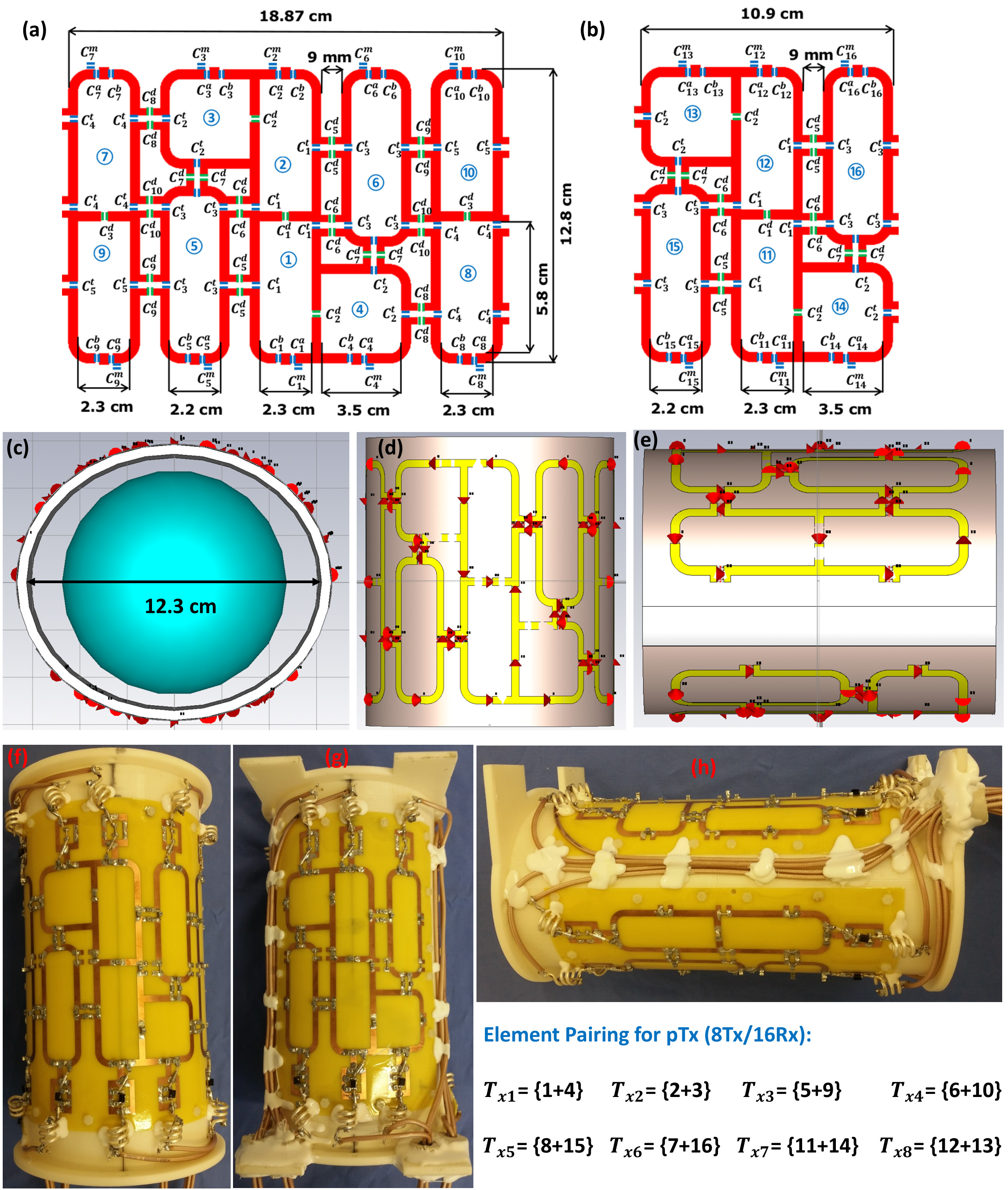
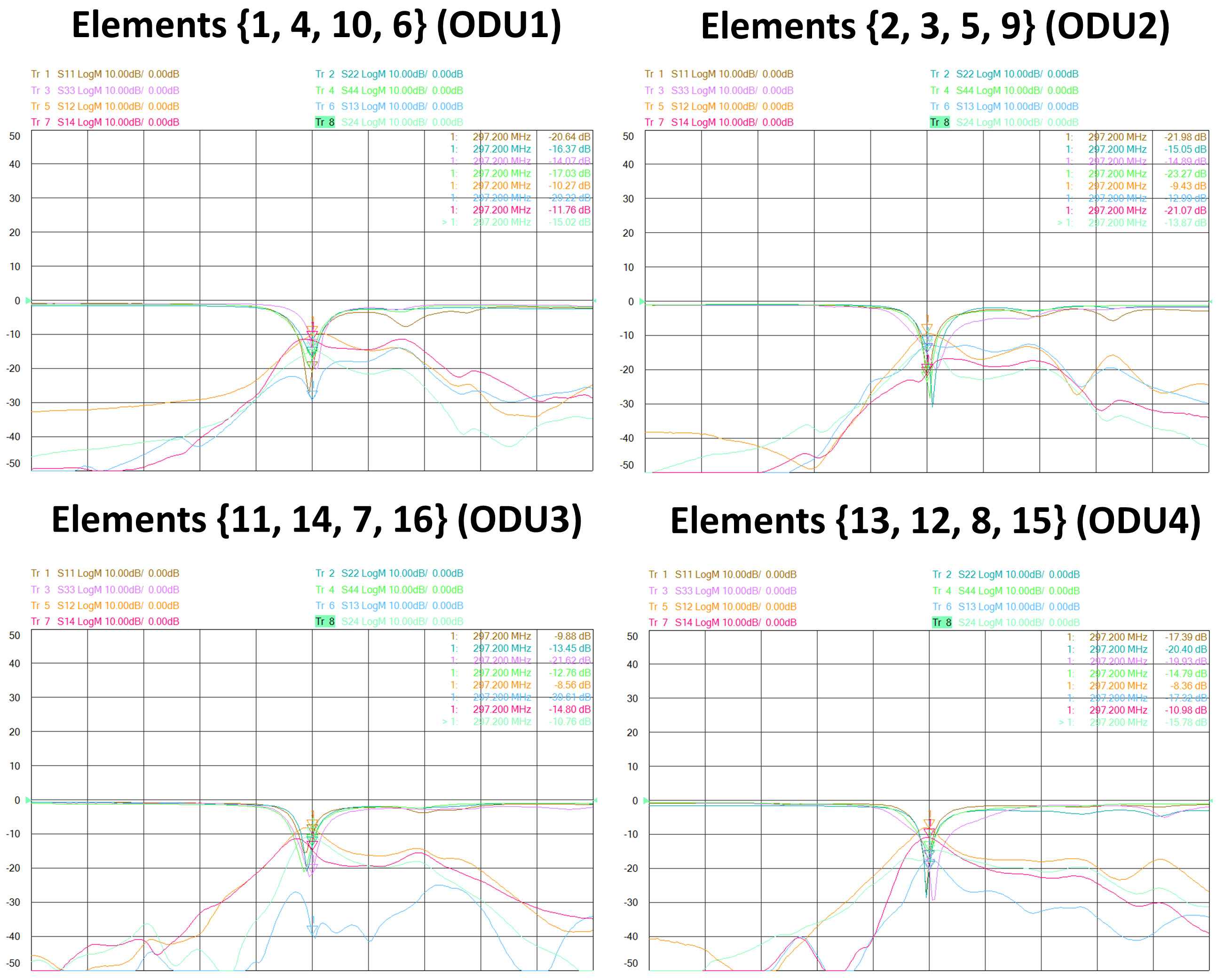
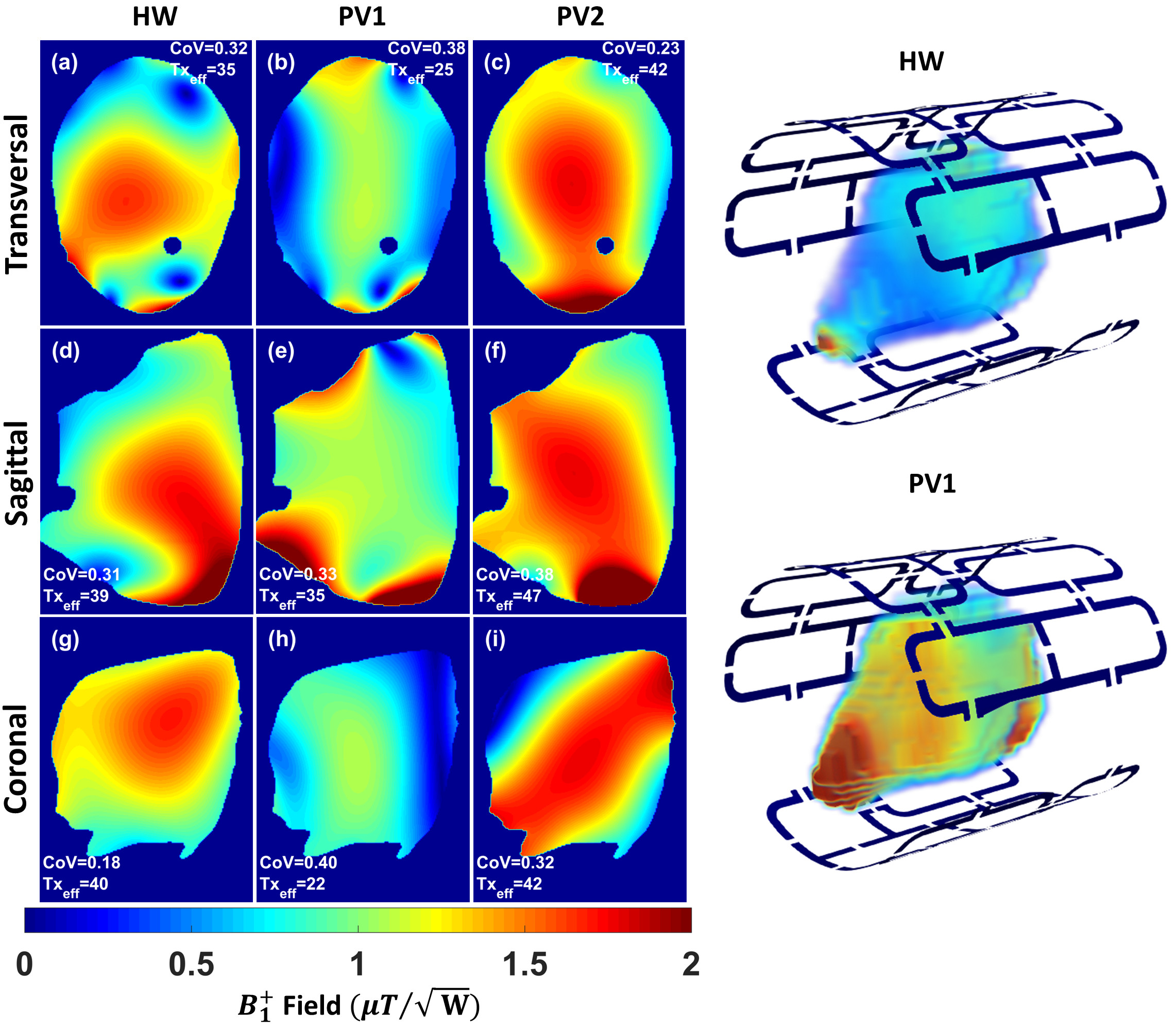
Figure 3 Simulated combined $$${B_1^+}$$$ field distribution in central transversal, sagittal, and coronal planes after static phase only $$${B_1^+}$$$ shimming for the 16 elements dedicated array within a voxel human heart (Billie) using two optimization cost functions ($$${FC_1}$$$ and $$${FC_2}$$$)7 compared to the hardware (HW) phases. The array was fed with 1W accepted power and all coil elements were fed with equal amplitudes. The $$$CoV$$$ and $$$Tx_{eff}$$$ in $$$\frac{\mu{T}}{\sqrt{kW} }$$$ were computed in the whole slice.