3251
Eddy-Currents Computations Using A Single-Layer Stream-Function Method
Sadeq s Alsharafi1, Haile Baye Kassahun1, Ahmed M Badawi1, and AbdEl-Monem M El-Sharkawy1
1Systems and Biomedical Engineering, Cairo University, Giza, Egypt
1Systems and Biomedical Engineering, Cairo University, Giza, Egypt
Synopsis
Eddy-currents induced by MRI gradient coils due to rapid switching result in undesirable thermal effects, field distortions and acoustic-noise. Efficient numerical computations are needed to analyze eddy-currents for complex configurations. The skin-depth adds an extra computational burden for numerical eddy-current computations since meshing in the skin-depth direction may be needed to achieve reliable computations during harmonic analysis. Here, we use a single-layer stream-function method (SSM) applying resistance compensation and compare our results to a multi-layer integral method (MIM) approach. We show that SSM method achieves accurate comparable results relative to both MIM and Ansys albeit at higher computational effeciency.
Introduction
Gradient coils are essential for MRI. However, rapid switching induces eddy-currents in MRI conducting structures causing undesired effects. In addition to traditional numerical methods (FEM, FDTD), other techniques were devised to analyze eddy-currents at higher computational efficiency such as the network analysis (NA) method1-3 and the more general Multilayer Integral Method (MIM)4. The eddy-current problem is reduced in both NA and MIM to a circuit equation. It is important to slice the metallic structures into multiple layers with a layer thickness less than the skin depth to obtain accurate results for eddy-current power dissipation calculations. The skin depth ($$$\delta$$$) depends on the excitation current frequency and the conductivity of the conductor ($$$\sigma$$$) where it is given by $$$\delta=\sqrt{\frac{1}{\pi\sigma\mu{f}}}$$$. At low-frequency excitation, where the skin depth($$$\delta$$$) is large compared to the thickness of the conductor(t), the eddy-currents are assumed to be uniform across the conductor thickness, Fig.1 (a). However, at the high frequencies, where the skin depth is smaller than the thickness of the conductor, the current densities are not uniform anymore, Fig.1 (b). The skin-depth effect has a great influence on the effective cross-section and subsequently on the resistance of the conductor. In this paper, a single-layer stream-function method (SSM) is used where the need to slice the metallic structure into multiple layers is eliminated. The circuit equation is constructed similar to NA and MIM while adding a resistance compensation factor to compensate for the skin effect.Methods
Similar to MIM, the metal structure's surface is meshed into a single layer of triangular elements, Fig. 2 (a). Each triangle node is locally numbered from 1 to 3 and has a global unique number4-6. The current density flowing inside a triangle is given as follows:$$\vec J_e=\vec e_1\phi_1+\vec e_2\phi_2+\vec e_3\phi_3$$ where $$$\vec e_1,\vec e_2$$$,and $$$ \vec e_3$$$ are the vectors facing the triangle nodes divided by the double area of the triangle, and $$$\Phi_1,\Phi_1$$$and$$$\Phi_3$$$ are the stream-function values at the triangle nodes. The source coil is considered as a thin wire coil with current source . The coil is discretized to number of segments where the segment vector is given as:$$\vec l_k=l_x\widehat{x}+l_y\widehat{y}+l_z\widehat{z}$$ The circuit equation is given as:$$R_{nm}\Phi+M_{nm}\frac{d\Phi}{dt}=-M_{n0}\frac {ds(t)}{dt}$$ where $$$\Phi$$$ is a vector that contains the stream-function of all nodes in the conducting structures. $$$M_{n0}$$$ is a vector containing the mutual inductance between the nodes 𝑛 on the metallic structures and the segments of the source coil. $$$R_{nm}$$$ and $$$M_{nm}$$$ are the resistance and inductance matrices due to the interaction of the nodes 𝑛 and m. Considering that the nodes n and m are shared among triangles N and M respectively. The matrices elements are given as: $$M_{n0}=\frac{\mu_0}{4\pi}\sum_{k=1}^{L}\sum_{N}^{}\int_{S}^{}\frac{\vec l_{k}.\vec e_{nN}}{|r_N-r_k|}ds$$ where $$$|r_N-r_k|$$$ is the distance between the coil segments k and the triangles N, L is the number of segments in the coil. $$R_{nm}=\frac{\eta}{\sigma t}\sum_{N}^{}\sum_{M}^{}\int_{S}^{}({\vec e_{nN}.\vec e_{mM}})ds$$ where t is the conductor’s thickness and $$$ \eta $$$ is the resistance compensation factor. $$M_{nm}=\frac{\mu_0}{4\pi}\sum_{N}^{}\sum_{M}^{}\int_{S'}^{}\int_{S}^{}\frac{\vec e_{nN}.\vec e_{mM}}{|r_M-r_N|}dsds'$$ where $$$|r_M-r_N|$$$ is the distance between the triangles N and M. The compensation factor $$$ \eta $$$ in $$$R_{nm}$$$ is used to compensate for the skin effect and it depends on the skin-depth and the conductor’s thickness7 where it is defined as: $$\eta=(\frac{t}{\delta})\frac{sinh(\frac{2t}{\delta})+sin(\frac{2t}{\delta})}{cosh(\frac{2t}{\delta})-cos(\frac{2t}{\delta})}$$ For harmonic analysis, the source current s(t) is considered as a sinusoidal with an amplitude $$$i_0$$$. The solution of the circuit first-order differential equation is given as:$$\Phi=-j\omega i_0(R_{nm}+jM_{nm})^{-1}M_{n0}$$ A tailored MIM framework was previously implemented8 in MATLAB. In this work, the SSM which considers the metallic structures as a single layer is compared to MIM and ANSYS which involve slicing the conductor into multilayers each of which is less than $$$\delta$$$. Initial computations are performed using a transverse self-shielded gradient and MRI cryostat only (first configuration). Further computations are performed including passive shielding (second configuration), Fig.2(b). The transverse gradient used here was previously designed using the discrete wire method9. The cryostat is a stainless-steel cylinder with 860mm diameter,1460mm height, 3.18mm thickness, and 96x10-8 resistivity. The passive shield is a copper cylinder of 844mm diameter, 1360mm height, 2mm thickness, and 1.7x10⁻⁸ resistivity. The current source is set to 600A with frequencies 10Hz up to 100KHz. The resolution of cryostat and the passive shield meshes has edge lengths less than 30mm and the coil tracks is divided into 20mm segments.Result and Conclusion
The skin depths of the cryostat and the passive shield are computed at specific frequencies as shown in Fig.1(c). The skin effect does not affect the resistance of the conductor if the skin depth is larger than the conductor’s thickness. Using the first configuration, the power dissipation in the cryostat are calculated using SSM, MIM, and ANSYS (3-layers for both MIM and Ansys) as tabulated in Tabel 1 showing the relative accuracy of SSM. Using the second configuration which involves the passive shielding, the power dissipation at both cryostat and passive shield are depicted in both Table 2 and Fig.3. The importance of using resistance compensation is also illustrated. Tables 1-2 also show the memory usage and computational time for each method. The results indicate that SSM achieves a relative accurate computation of eddy-currents power dissipation at higher computational efficiency.Acknowledgements
Sadeq S. Alsharafi is partially financially supported for his Ph.D program at Cairo University by the Yemeni ministry of higher education. Haile Kassahun is financially supported by the African Biomedical Engineering Mobility (ABEM) for his Ph.D. program at Cairo University. The ABEM project is funded by the Intra-Africa Academic Mobility Scheme of the Education, Audiovisual, and Cultural Executive Agency of the European Commission.References
- Takahashi T. Numerical analysis of eddy current problems involving z gradient coils in superconducting MRI magnets. IEEE transactions on magnetics. 1990;26(2):893-896.
- Sablik M, Beissner R, Choy A. An alternative numerical approach for computing eddy currents: Case of the double-layered plate. IEEE transactions on magnetics. 1984;20(3):500-506.
- Kidane TK, Edelstein WA, Eagan TP, et al. Active-passive shielding for MRI acoustic noise reduction: Network analysis. IEEE transactions on magnetics. 2006;42(12):3854-3860.
- Sanchez Lopez H, Freschi F, Trakic A, et al. Multilayer integral method for simulation of eddy currents in thin volumes of arbitrary geometry produced by MRI gradient coils. Magnetic resonance in medicine. 2014;71(5):1912-1922.
- Lemdiasov RA, Ludwig R. A stream function method for gradient coil design. Concepts in Magnetic Resonance Part B: Magnetic Resonance Engineering: An Educational Journal. 2005;26(1):67-80.
- Kameari A. Transient eddy current analysis on thin conductors with arbitrary connections and shapes. Journal of Computational physics. 1981;42(1):124-140.
- Kazimierczuk MK. High-frequency magnetic components. 2nd ed: John Wiley & Sons; 2014.
- Alsharafi SS, Badawi AM, El-Sharkawy AM. A Comparative Study for Evaluating Passive Shielding of MRI Longitudinal Gradient Coil. 43rd Annual International Conference of the IEEE Engineering in Medicine & Biology Society (EMBC); 2021.
- Alsharafi SS, Badawi AM, El-Sharkawy AM. Design of a Self-Shielded Transverse MRI Gradient Coil Taking into Account Track Width. Paper presented at: 2020 IEEE 5th Middle East and Africa Conference on Biomedical Engineering (MECBME)2020.
Figures
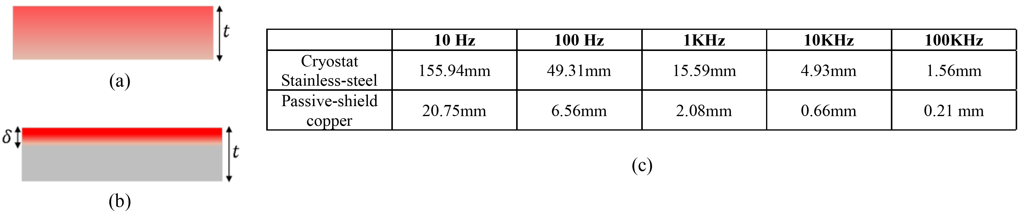
Fig.1:
a) Demonstration of uniform eddy current distribution in the cross-section of
the conductor in case of low frequency where the skin depth is > the
conductor thickness. b) Eddy current condenses at the surface within the skin
depth of the conductor in case of high-frequency excitation as the skin depth ≪ the conductor thickness. c) The skin-depth δ for the used metallic
structures at selected frequencies.
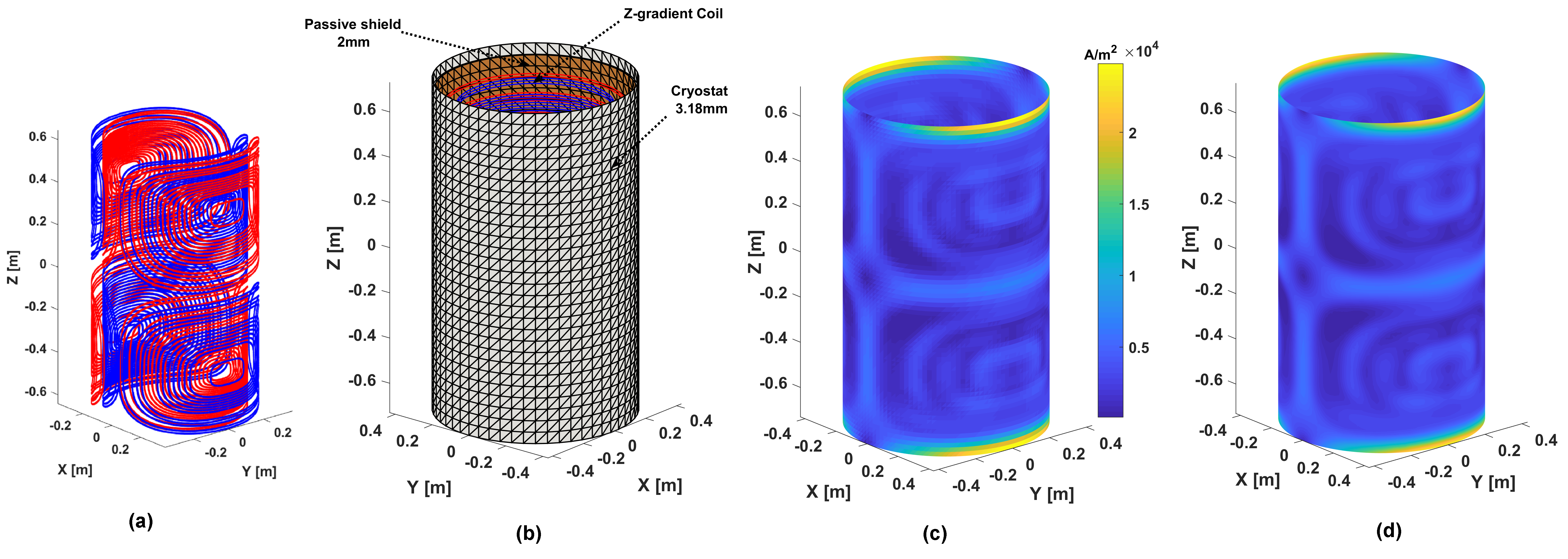
Fig.2:
(a) 3D plot of the self-shielded x-gradient coil. (b) The cryostat and passive
shield are meshed with triangular elements. Computed current density (magnitude)
distribution on the cryostat at 100Hz as computed using SSM (c) and Ansys (d).
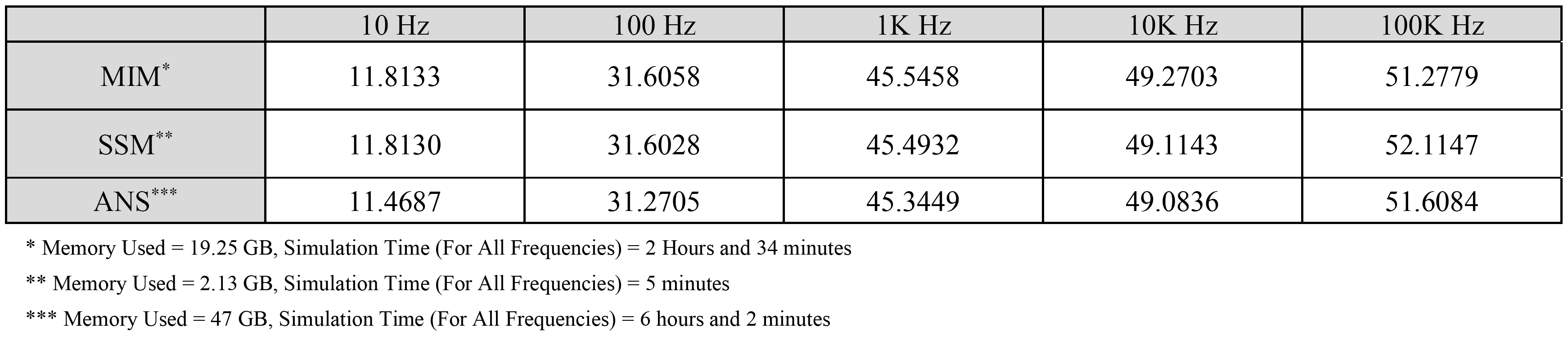
Table
1: The power dissipation at the cryostat induced by x-gradient calculated from
the MIM, SSM, and ANSYS.
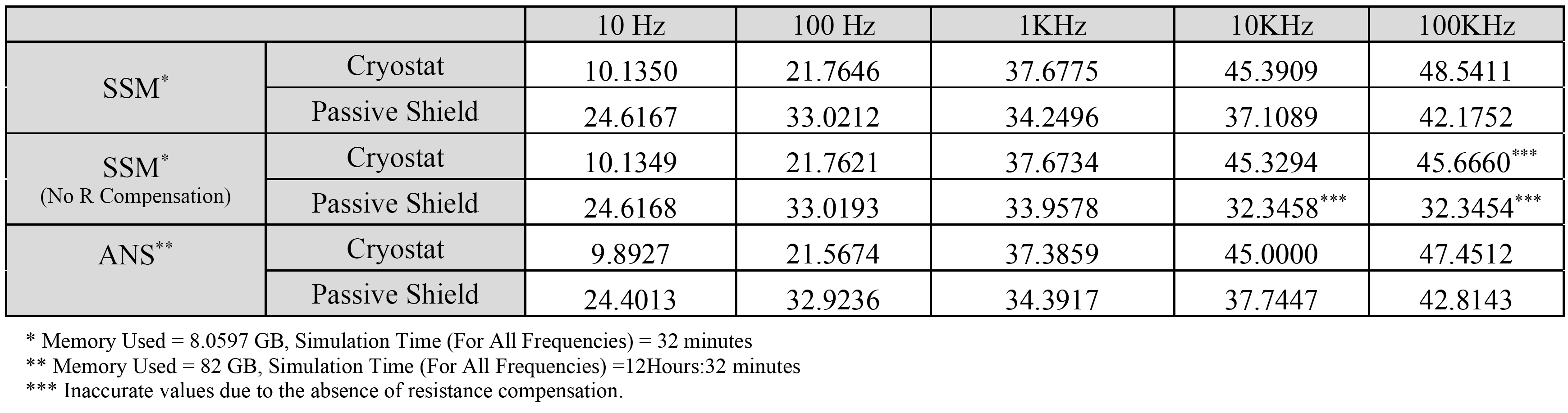
Table
2: The power dissipation induced by a passively shielded x-gradient at both the
cryostat and passive shield computed by SSM and ANSYS.
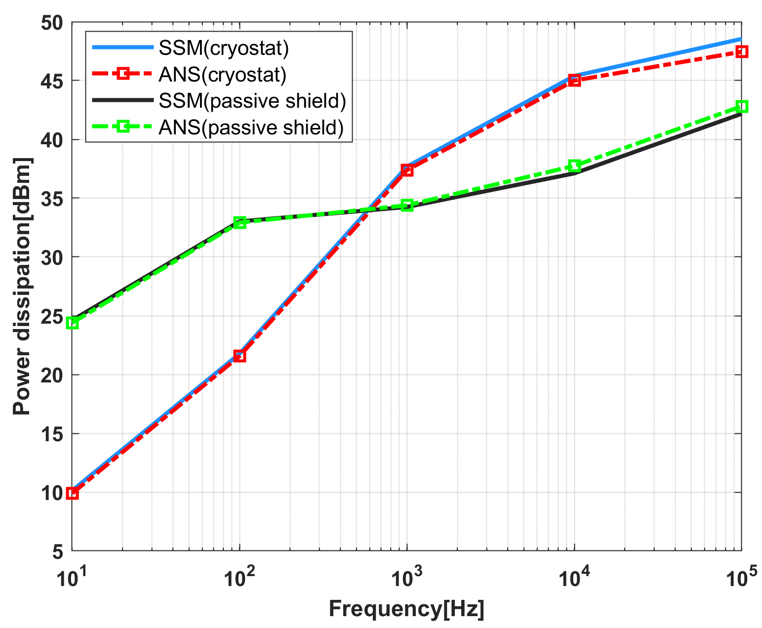
Fig.3:
The eddy-current power dissipation at the cryostat and passive shield induced
by the self-shielded x-gradient coil versus frequency.
DOI: https://doi.org/10.58530/2022/3251