3250
Actively Shielded Two-channel Transverse MRI Gradient Coil Numerical Design Using Discrete Wire Method1Systems and Biomedical Engineering, Cairo University, Cairo, Egypt
Synopsis
A two-channel, self-shielded, cylindrical, transverse gradient coil is numerically designed. The four quadrants of both the inner and outer cylinders were each divided into two sections. All symmetric inner sections of the primary and corresponding shielding coil turns are assigned to the first channel where the outer enclosing sections belong to the second channel. Quasi-elliptic curves are used for coil tracks design. Achieving a comparable target gradient field, the DC dissipated power of a two-channel coil is lower compared to a conventional coil designed with similar dimensions and number of turns by at least 20%, thereby reducing ohmic losses.
Introduction
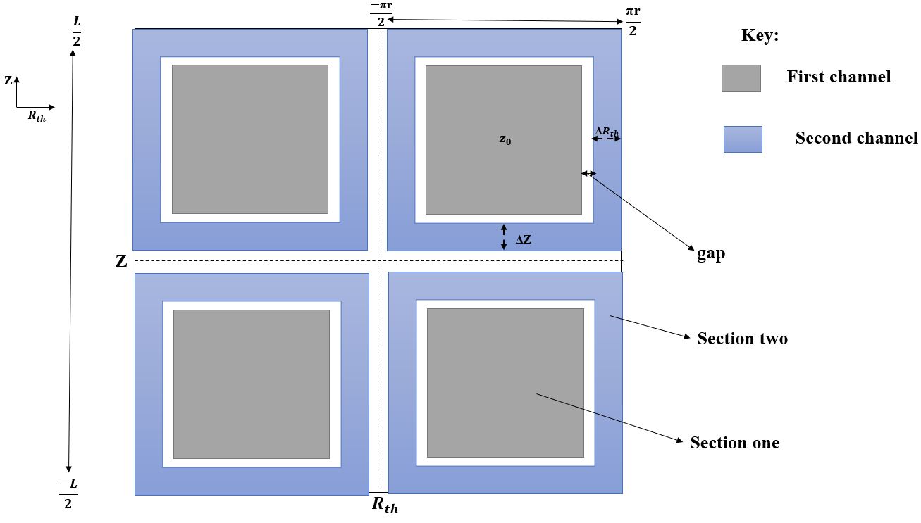
Recently, we introduced a more power-efficient two-channel biplanar z-gradient coil numerical design by dividing the conventional biplanar coil surface into two sections in the radial direction1. In this work, we investigate the DC power efficiency of a two-channel, cylindrical, self-shielded, transverse gradient coil numerical design. A discrete wire method based on quasi-elliptic curve approximation of the coil contours is used 2–5. Here, each of the four quadrants of the primary and shielding transverse gradient coil is divided into two sections (Figure 1). The first channel consists of the inner sections whereas, the second channel is assigned to the outer enclosing sections. Quasi-elliptic functions were used to design the coil tracks3. The dimensions of each section were varied along the longitudinal and circumferential directions until the most power-efficient design is obtained. A conventional transverse gradient coil with comparable dimensions and similar target gradient strength is also designed to compare the DC power efficiency.Methods
Figure 1 illustrates the sectioning of the proposed two-channel design. As shown in the figure, each quadrant has two sections separated by a small gap. Section two has dimensions of $$$\Delta R_{th}$$$ and $$$\Delta Z$$$ in the circumferential and longitudinal directions, respectively. Quasi-elliptic curves similar to3,5 are used to parameterize the tracks for each section. Similar surface division and track-curve shape functions were also applied for the shielding coil. The Biot-Savart law: $$$B=\frac{μ_0I}{4π}∫\frac{dl×(r-l)}{|r-l|^3}$$$ was used to calculate the magnetic field produced by the tracks of each section. Here, $$$μ_0$$$ is the permeability of free space, $$$B$$$ is magnetic flux density, $$$dl$$$ is the track segment vector, and $$$(r-l)$$$ is a vector from the track element to the DSV point. The target is to minimize the objective function4 $$$f= -λG_x+(1- λ) lin_{er}$$$, where $$$lin_{er}=\frac{G_{max}-G_{min}}{G_{max}+G_{min}}×2×100\%$$$ is the linearity error over the predetermined diameter-of-spherical-volume (DSV), $$$G_{max}$$$ and $$$G_{min}$$$ are the calculated maximum and minimum gradients, respectively, $$$G_x=\frac{1}{M}∑_{m=1}^MG_m$$$ is the average gradient, where, M=97 is the total number of points over the DSV and $$$λ$$$ is the weighting factor to balance between maximizing $$$G_x$$$ and minimizing $$$lin_{er}$$$. Here, we chose λ=0.95. Optimization is subject to the constraints: $$$SHR>85\%$$$ and $$$wire\ spacing≥\Delta d$$$, where $$$SHR$$$ is the shielding ratio defined as: $$$(1-\frac{B_{sp}}{B_p})×100\%$$$ and $$$B_{sp}$$$ / $$$B_{p}$$$ are the average stray magnetic flux densities of the shielded / unshielded (primary) coils, respectively5. Here, $$$\Delta d$$$ is the minimum distance between consecutive contours. The design variables for the optimization are the two-channel currents ($$$I_1$$$, $$$I_2$$$), the quasi-elliptic parameters, the center of the tracks ($$$z_0$$$), and the track locations of all quadrants. In this work, the built-in MATLAB function fmincon was used for the optimization. The above optimization steps were performed for eight different configurations by varying $$$\Delta R_{th}$$$ and $$$\Delta Z$$$ from 2.7cm-9.7cm and 5.185cm-12.185cm, respectively with an incremental length =1cm for the primary coil. The dimensions $$$\Delta R_{th}$$$ and $$$\Delta Z$$$ for the shielding coil were also proportionally updated. The total number of turns for the two-channel primary and shielding coils were kept the same as that of the corresponding conventional primary and shielding coils, respectively. However, the number of turns of each section for a particular two-channel configuration varies proportionally with its dimensions ($$$\Delta R_{th}$$$ and $$$\Delta Z$$$). We used a primary coil of length=1.286m, shielding coil length=1.326m, radius of primary coil=0.32m, radius of shielding coil=0.37m, total number of turns for primary=88, total number of turns for shielding =52, target gradient field= 30mT/m, cryostat radius=0.43m, cryostat length=1.46m, and DSV diameter=0.5m for each configuration5.Results
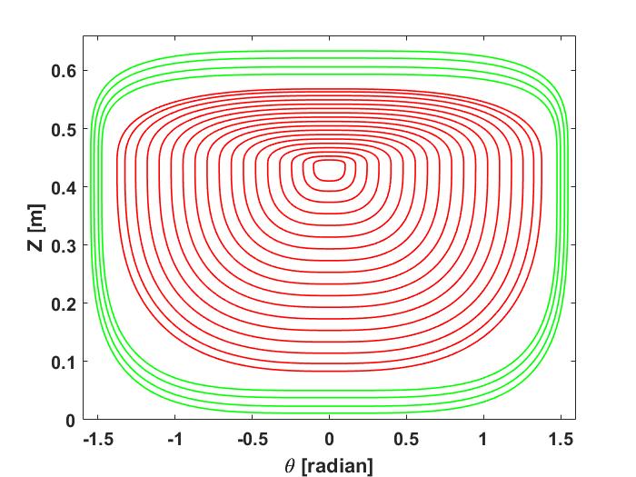
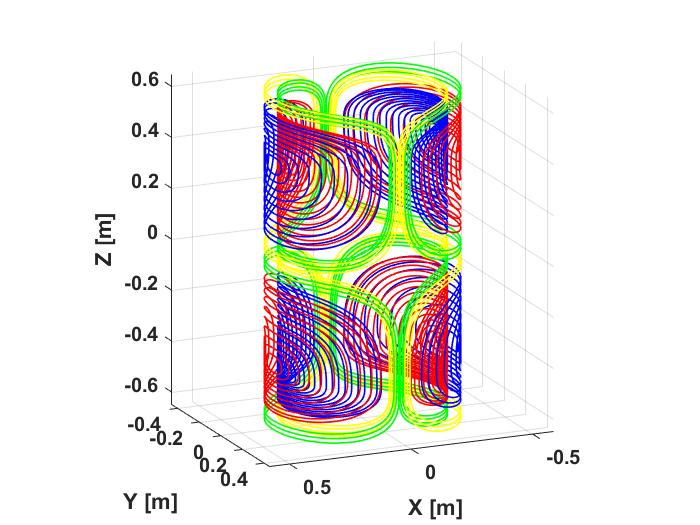
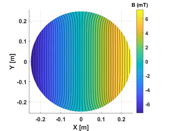
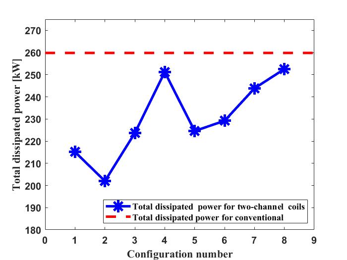
The optimization process resulted in a total of 8 different configurations of two-channel coils from which the configuration of least DC power dissipation was chosen. Figure 2 shows the coil patterns of the first and second sections for a single quadrant primary coil configuration. Figure 3 shows the 3D winding pattern of the optimal self-shielded two-channel coil configuration. In that case, channel one and two had currents of 602.30A and 456.72A, respectively, whereas, the conventional coil had a current of 638.80A. Therefore, the proposed two-channel configuration can generally produce the same gradient field with less driving current compared to the conventional coil. Figure 4 shows the gradient field map generated by the optimal two-channel coil for a transverse plane. Linearity errors for both the two-channel and conventional single-channel coils were around 10%. The two-channel coil had also comparable maximum field deviation (5.95%) with that of the conventional coil (5.29%). The calculated smallest distance between consecutive contours was around 5mm where the copper winding tracks are assumed to have a 2mm thickness and a 3mm width. Accordingly, the dissipated power for each coil design is calculated. Figure 5 shows the DC power dissipation comparison of eight configurations of the two-channel self-shielded transverse gradient coil as well as the conventional single-channel coil. As shown in Figure 5, the two-channel coil design with $$$\Delta R_{th}$$$(3.7cm) and $$$\Delta Z$$$(6.185cm) for the primary coil has the least dissipated power (~202kW) which is less than that of the conventional coil (~260kW).Discussion and Conclusions
In this work, we designed a more power-efficient, self-shielded, two-channel transverse-gradient coil. In the future, the design of multi-channel, transverse, gradient coils may be further investigated to observe if more power reduction can be achieved.Acknowledgements
Haile Kassahun is financially supported by the African Biomedical Engineering Mobility (ABEM) for his Ph.D. program at Cairo University. The ABEM project is funded by the Intra-Africa Academic Mobility Scheme of the Education, Audiovisual, and Cultural Executive Agency of the European Commission. Sadeq S. Alsharafi is partially financially supported for his Ph.D. program at Cairo University by the Yemeni ministry of higher education.References
1.Kassahun HB, Alsharafi SS, Badawi AM, El-Sharkawy AM. Towards a More Power Efficient Two-Channel Biplanar Z-Gradient Coil Design Using Target Field Method, Proc. 29th Sci. Meet. Int. Soc. Magn.Reson. Med. and SMRT, p. 3097, April 2021.
2. Wang Y, Xin X, Liu F, Crozier S. Spiral Gradient Coil Design for Use in Cylindrical MRI Systems. IEEE Trans Biomed Eng. 2018;65(4):911-920.
3. Wang Y, Liu F, Zhou X, Crozier S. Design of Transverse Head Gradient Coils Using a Layer-sharing Scheme. J Magn Reson. 2017; 278:88-95.
4. Du X, Zhu Z, Zhao L, et al. Design of Cylindrical Transverse Gradient Coil for 1.5 T MRI System. IEEE Trans Appl Superconductivity, 2012;22(3).
5. Alsharafi SS, Badawi AM, El-Sharkawy AM. Design of a Self-Shielded Transverse MRI Gradient Coil Taking into Account Track Width, 2020 IEEE 5th Middle East and Africa Conference on Biomedical Engineering (MECBME), 2020.
Figures