3249
Transient Computations of Eddy-Currents Induced by an Amplitude-Modulated Sinusoidal Gradient Pulse
Sadeq S Alsharafi1, Haile Baye Kassahun1, Ahmed M Badawi1, and AbdEl-Monem M El-Sharkawy1
1Systems and Biomedical Engineering, Cairo University, Giza, Egypt
1Systems and Biomedical Engineering, Cairo University, Giza, Egypt
Synopsis
Eddy-currents are generated in MRI scanners’ metallic structures due to the rapid switching of gradient coils. They may result in image distortions and induce acoustic-noise particularly for fast/spiral sequences. Transient eddy-currents computations can be used to understand the extent of such effects. In this work, a numerical framework was devised to compute transient eddy-currents induced by an amplitude-modulated sinusoidal pulse for a longitudinal gradient coil configuration. Stream functions representation of eddy-currents, Multilayer Integral Method, and an excitation current with amplitude-modulated sinusoidal function are used to solve the circuit equation and efficiently compute transient eddy-currents generated in the cryostat.
Introduction
Rapid switching of gradient coils generates undesirable eddy-currents in the surrounding metallic structures of the MRI scanner including spiral K-space acquisition. It is noted that gradient pulse functions used for spiral imaging may involve amplitude-modulated sinusoidal functions1. Harmonic and transient eddy-currents analysis have been previously described2,3. In both the network analysis (NA) method2 and Multilayer Integral Method (MIM)3, the eddy-currents problem is reduced to a circuit equation representation (differential equation of the first order). The circuit equation in the NA method represents directly eddy-currents while it represents stream functions in the MIM method (eddy-currents are calculated using stream functions). Only transient eddy-currents computations for a trapezoidal gradient pulse have been performed in a previous study2. In this work, we compute transient eddy-currents induced by an amplitude-modulated sinusoidal pulse in the scanner’s cryostat. As we have previously shown, we now use an adapted MIM computational framework for generality4 where we solve here the circuit equation in the time domain for an amplitude-modulated sinusoidal excitation current.Methods
Same dimensions of a self-shielded unconnected z-gradient coil and cryostat as in references2,4 are used in this work. The cryostat is meshed into a single layer of triangular elements, (Fig.1). Each triangle node is locally numbered from 1 to 3 and globally labeled by a unique number3,5,6. The current density flowing inside a triangle is given as follows:$$\vec J_e=\vec e_1\phi_1+\vec e_2\phi_2+\vec e_3\phi_3$$ where $$$\vec e_1,\vec e_2$$$ and $$$\vec e_3$$$ are the vectors facing the triangle nodes divided by the double area of the triangle, $$$\Phi_1,\Phi_2$$$ and $$$\Phi_3$$$ are the stream function values at the triangle nodes. The source coil is considered as a thin wire coil carrying a time-varying current s(t). In the time domain, the circuit equation is given as:$$R_{nm}\Phi+M_{nm}\frac{d\Phi}{dt}=-M_{n0}\frac {ds(t)}{dt}$$ where $$$\Phi$$$ is a vector that contains the stream function of all nodes in the conducting structure. $$$M_{n0}$$$ is a vector containing the mutual inductance between the arbitrary nodes 𝑛 on the metallic structure and the segments of the source coil. $$$R_{nm}$$$ and $$$M_{nm}$$$ are the resistance and inductance matrices due to the interaction of any arbitrary nodes n and m. The matrices $$$M_{n0},R_{nm}$$$ and $$$M_{nm}$$$ are constructed as in references3,4,7. For transient solution, the current source s(t) is represented by amplitude-modulated sinusoidal function which is described as $$$s(t)=At\ sin(2\pi ft+\theta)$$$ and its derivate is given as: $$\frac {ds(t)}{dt}=A\ sin(2\pi ft+\theta)+2Af\pi t\ cos(2\pi ft+\theta)$$ where A is a scalar (At represents the time-dependent current magnitude), f is the frequency of the pulse, and θ is a general phase term. The circuit equation above is a first-order differential equation and its solution is given as:$$\Phi(t)=\Phi(0)\ e^{(-λt)}+U[\frac {1}{(4π^2 f^2+λ^2)^2}AQ[[2πfλ (4π^2 f^2 t+λ^2 t-2λ)]\ cos(2πft+θ)+(16π^4 f^4t +4π^2f^2λ^2 t-4π^2f^2λ+λ^3)\ sin(2πft+θ)+4πfλ^2e^{(-λt)}]]$$ where $$$Q=-U^{-1}M_{nm}^{-1}M_{n0}$$$ , $$$\Phi(0)$$$ is the initial value of the stream functions. λ and U are the eigenvalue vector and eigenvector matrix respectively of $$$M_{nm}^{-1}R_{nm}$$$. The z-gradient used in our simulations has a primary coil radius of 330mm and a secondary coil radius of 420 mm with 116 total turns. The cryostat is a stainless-steel cylinder with 450mm radius,1700mm height, 3.18mm thickness, and 96x10-8 resistivity. The parameters of the excitation pulse are set as A=104, f=1KHz, and θ=0. The resolution of the cryostat meshes has edge lengths less than 30mm and the coil tracks is divided into 20mm segments. Computations are performed using MATLAB (MathWorks, MA).Result and Conclusion
Eddy-currents induced by an amplitude-modulated sinusoidal function are calculated for a time interval from 0 to 11 ms with a 2μs time step. The implemented framework shows high efficiency in terms of time and memory relative to other commercial EM computational tools4 as was previously shown. The whole simulation including the constructions of the matrices and solving the circuit equation takes around 20mins while the memory used is approximately 2GB. Fig.2 shows the magnitude of eddy-currents density distribution on the cryostat at selected ten-time points labeled in the figure. The magnitude of eddy-currents at arbitrary points A and B on the cryostat (depicted in Fig.1) are plotted along with the excitation amplitude-modulated sinusoidal pulse versus time in Fig.3. The results show the ability of the framework to perform temporal eddy-currents computations for an amplitude-modulated sinusoidal function which, up to our knowledge has not been previously shown. The computational framework achieved in this work may be further developed applying more realistic gradient pulses used during spiral imaging sequences to compute resultant eddy-currents as well as analyzing their effect on MR imaging associated distortions. Also, the computation can be performed using transverse gradient coil configurations.Acknowledgements
Sadeq S. Alsharafi is partially financially supported for his Ph.D program at Cairo University by the Yemeni ministry of higher education. Haile Kassahun is financially supported by the African Biomedical Engineering Mobility (ABEM) for his Ph.D. program at Cairo University. The ABEM project is funded by the Intra-Africa Academic Mobility Scheme of the Education, Audiovisual, and Cultural Executive Agency of the European Commission.References
- Brown RW, Cheng YCN, Haacke EM, Thompson MR, Venkatesan R. Magnetic Resonance Imaging: Physical Principles and Sequence Design. John Wiley & Sons; 2014.
- Kidane TK, Edelstein WA, Eagan TP, et al. Active-passive shielding for MRI acoustic noise reduction: Network analysis. IEEE transactions on magnetics. 2006;42(12):3854-3860.
- Sanchez Lopez H, Freschi F, Trakic A, et al. Multilayer integral method for simulation of eddy currents in thin volumes of arbitrary geometry produced by MRI gradient coils. Magnetic resonance in medicine. 2014;71(5):1912-1922.
- Alsharafi SS, Badawi AM, El-Sharkawy AM. A Comparative Study for Evaluating Passive Shielding of MRI Longitudinal Gradient Coil. 43rd Annual International Conference of the IEEE Engineering in Medicine & Biology Society (EMBC); 2021.
- Kameari A. Transient eddy current analysis on thin conductors with arbitrary connections and shapes. Journal of Computational physics. 1981;42(1):124-140.
- Lemdiasov RA, Ludwig R. A stream function method for gradient coil design. Concepts in Magnetic Resonance Part B: Magnetic Resonance Engineering: An Educational Journal. 2005;26(1):67-80.
- Alsharafi SS, Badawi AM, El-Sharkawy AM. Design of a Self-Shielded Transverse MRI Gradient Coil Taking into Account Track Width. Paper presented at: 2020 IEEE 5th Middle East and Africa Conference on Biomedical Engineering (MECBME)2020.
Figures
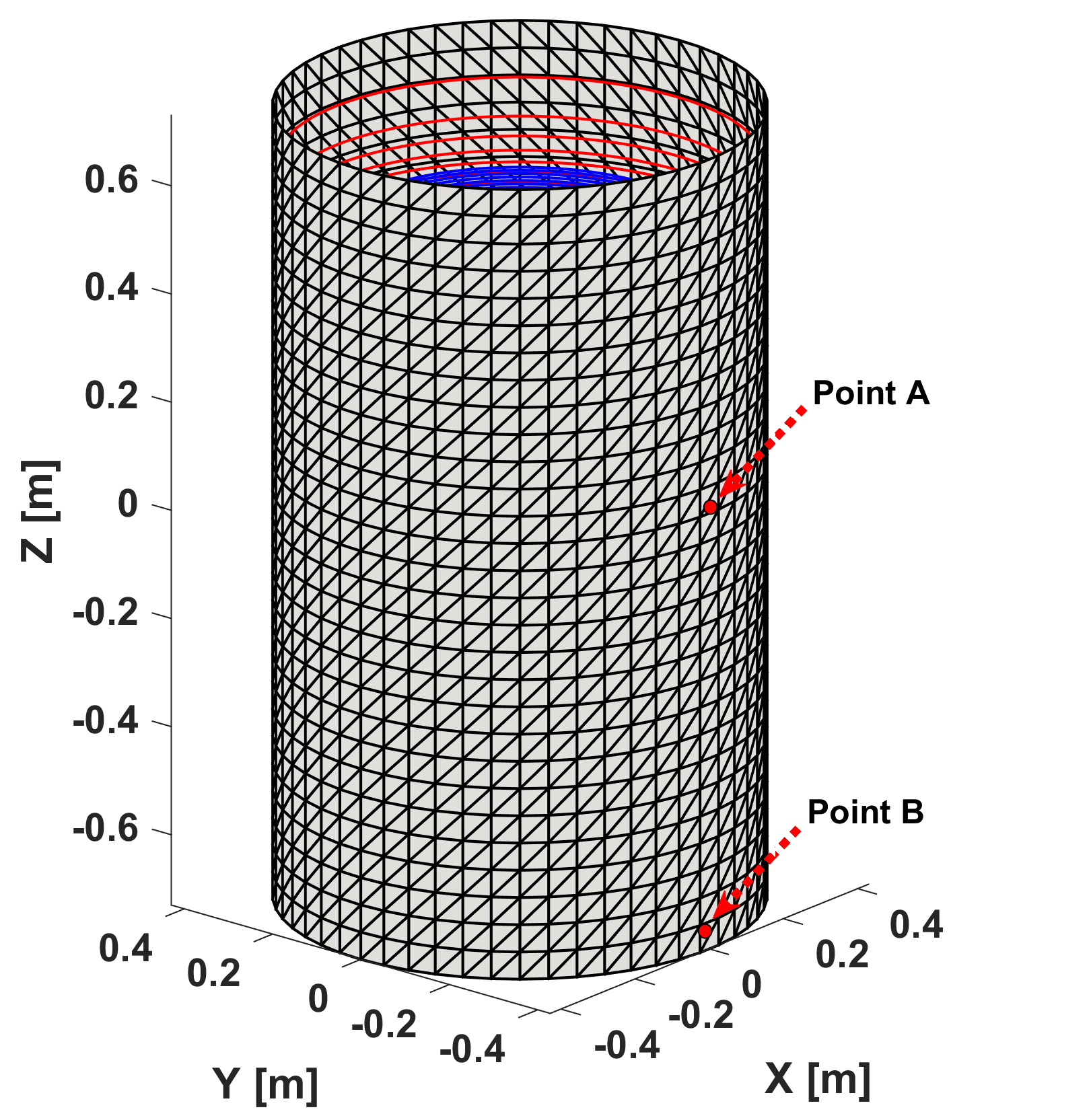
Fig.1: 3D plot of the configuration used in the
simulation including the cryostat and the z-gradient coil. The cryostat cylinder
is meshed into structured triangular elements.
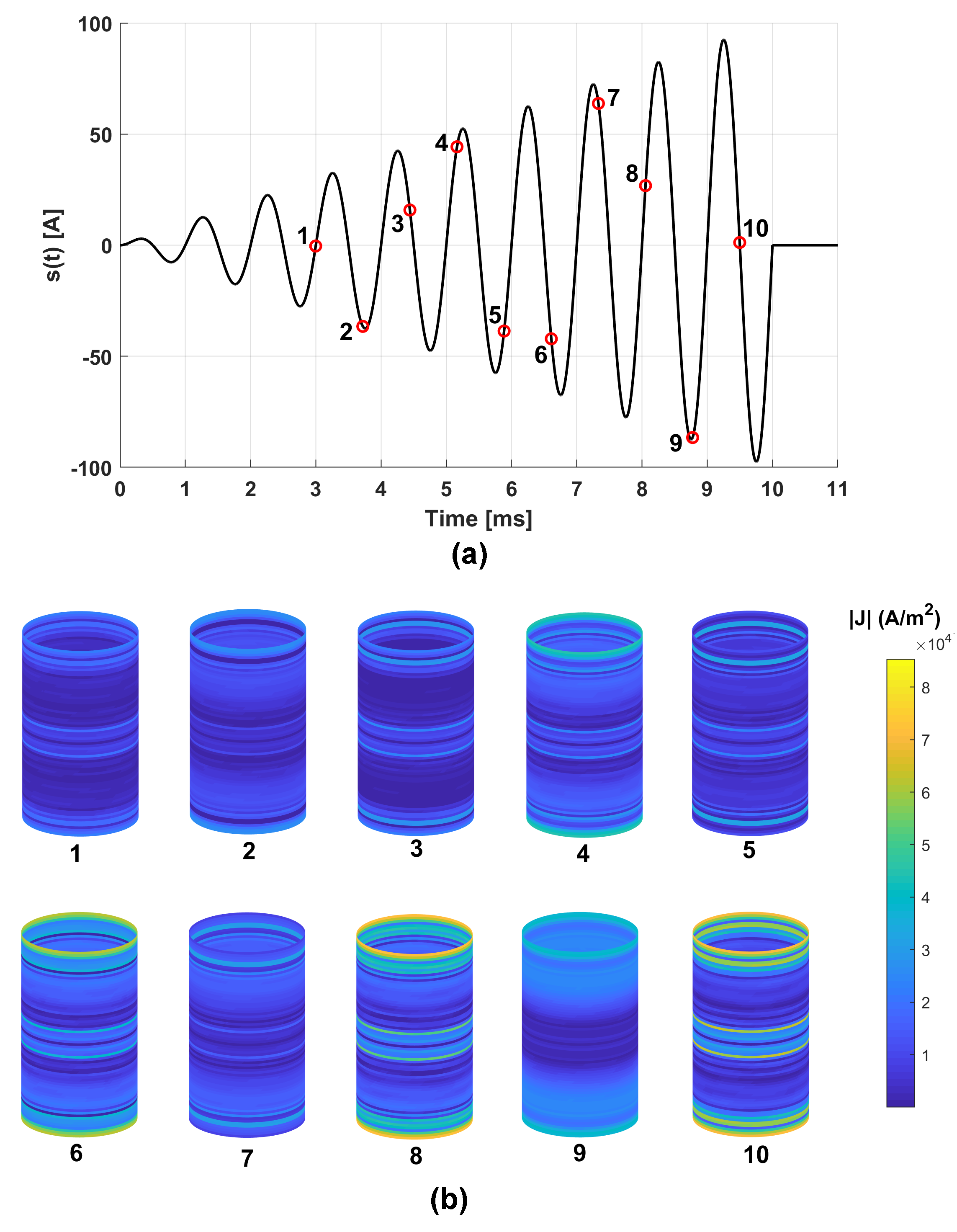
Fig.2: (a) The excitation spiral current pulse illustrating
10-time
points and (b) the corresponding eddy-current density distribution on the
cryostat.
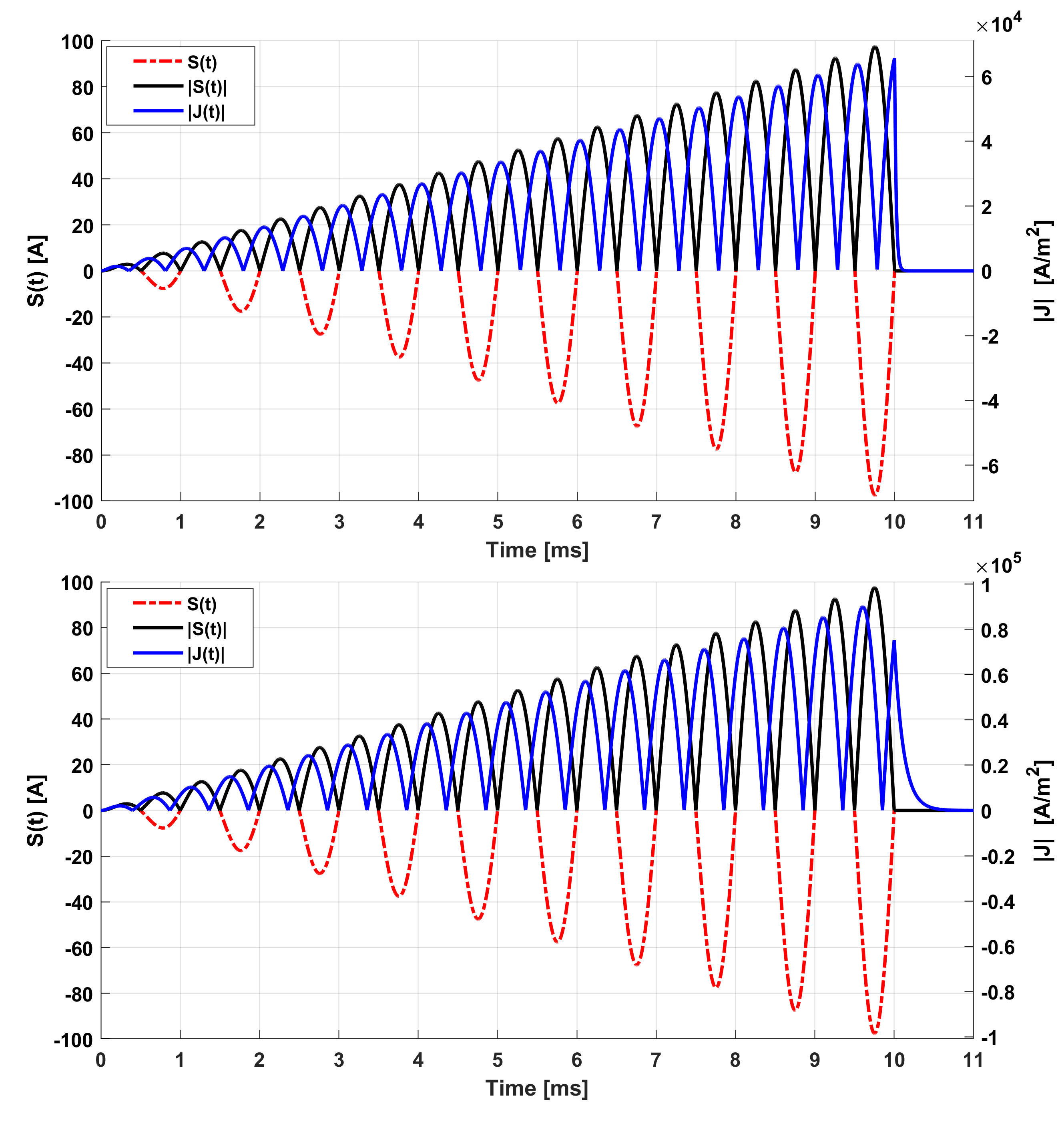
Fig.3: Eddy current magnitude at
arbitrary points A (Top) and B (Bottom) of the cryostat induced by the
excitation amplitude-modulated sinusoidal waveform S(t).
DOI: https://doi.org/10.58530/2022/3249