3244
A 2kW non-magnetic RF power amplifier with negative feedback for 5T MRI proton imaging1Chongqing University of Technology, Chongqing, China, 2Lauterbur Imaging Research Center, Shenzhen Institutes of Advanced Technology, Chinese Academy of Sciences, Shenzhen, China, 3Key Laboratory for Magnetic Resonance and Multimodality Imaging of Guangdong Province, Shenzhen, China
Synopsis
Parallel transmission technology has attracted much attention because of its advantages of uniform excitation and artifact correction in ultra-high field. A 2kW non-magnetic prototype RF amplifier for 5T multi-channel parallel transmission (pTx) is presented. It is equipped with analogic feedback loops and provides a high linearity up to peak output power. It maintains excellent fidelity performance even without a circulator.
Introduction
Parallel transmission technology has high significance in Ultra-high field (UHF) MRI systems[1]. Inter-channel coupling limits the application of multi-channel parallel transmission systems[2]. The closer distance between MRI radio frequency power amplifier (RFPA) and coils allows compensation of these problems and even an improvement[3]. What’s more, the power transmission loss can be reduced by shortening the transmission distance, also reducing the design difficulty and the cost of RFPA. However, shortening the distance means that circulators in the magnet-room are prohibited. The transmit coils will serve directly as the output load of the amplifier. When the transmit coil faces different scanning objects, its equivalent impedance will change[2]. The load effect of the coil will cause the output mismatch of the RF power amplifier, resulting in the deterioration of linearity performance of RFPA[3]. Then, a large variable range of the output gain and phase of the amplifier will cause MRI imaging artifacts. This work presents a non-magnetic prototype RF power amplifier for 5.0T MRI pTx system that can be used in magnet-room. An analog negative feedback technique is proposed to make the RF power amplifier work more stable in the face of normal load mismatch. High peak power capability and linearity were obtained.Methods
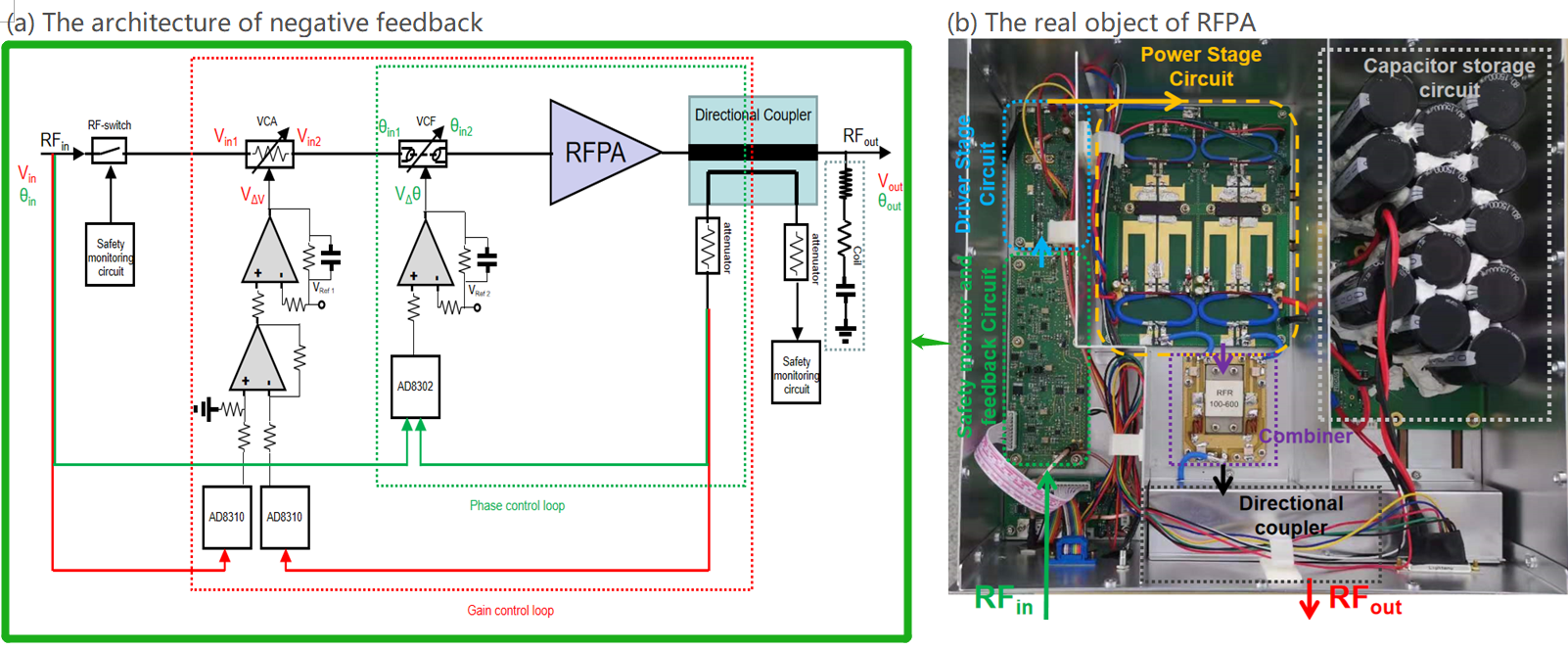
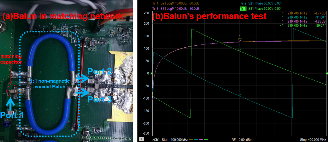
This RFPA for 5.0T MRI contains a three-stage amplification structure. There are two driver stages in series and the last is the power stage. In the final power stage, two LDMOS power tubes with high standing wave tolerance (NXP MRFX1K80N) were combined in parallel to obtain the expected output power of about 2KW. The hardware architecture is shown in figure 1(b). The lumped Wilkinson power divider was used to make the structure of RPFA more compact. In order to reduce running noise, water cooling heatsink is adopted.When RFPA is used without circulators in magnet-room, it requires some improvements to traditional amplifiers. Firstly, traditional magnetic resonance amplifiers use transmission line transformers with magnetic cores to participate in the impedance matching design. We designed a non-magnetic balun using an about 1/8 wavelength coaxial line, and used a matching capacitor to compensate for the deteriorating input standing wave performance due to the introduction of balanced windings, as shown in figure 2. The matching circuit design of power amplifier circuit was specially designed by ADS simulation using the actual SNP scattering parameters of this non-magnetic balun. Secondly, to avoid the reflected power generated by mismatched load damaging the power tubes,a safety monitoring circuit is used to cut off the RF input in time when the reflected power is too large. Last but most importantly, mismatched load can change the output gain and phase of a power amplifier. Thus a voltage controlled attenuator (VCA) and a voltage controlled phase shifter (VCP) were connected in series in the RF small signal input chain. When the output gain or phase of RFPA changes due to load-effect or other reasons, the VCA or VCF will reversely compensate the change, keeping the linearity of the amplifier. The larger the feedback gain, the less nonlinear of RFPA, but the feedback loop may be unstable. According to the bandwidth requirements of the pulse train , the appropriate feedback gain was obtained and the loop stability was guaranteed by simulating and practical debugging. The architecture of negative feedback is shown in figure 1(a).
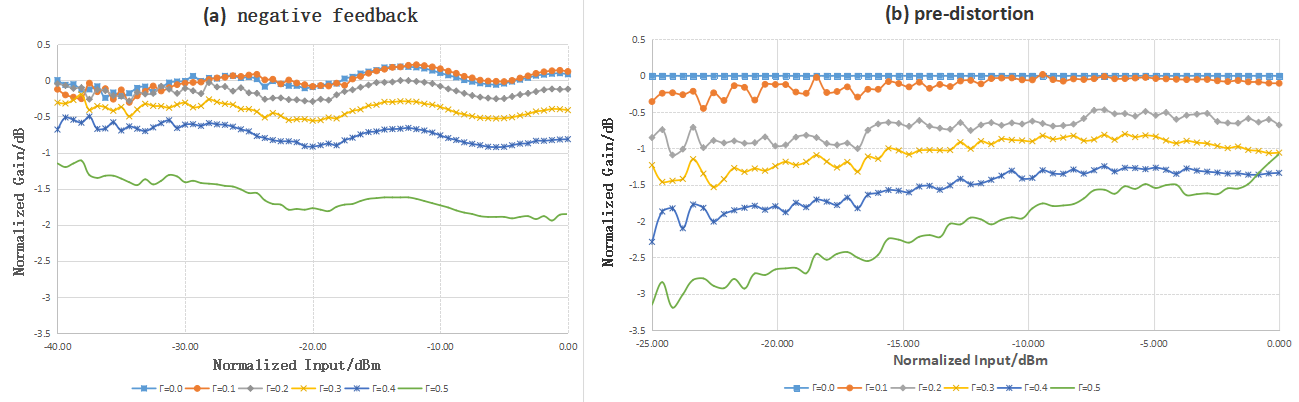
To test the actual performance of power amplifier, the mismatched load was built by a series inductor in front of the output port of RFPA. And, to evaluate the ability of anti-load disturbance of RFPA, the pre-distortion linearization correction technique of traditional MRI RFPA was used for comparison.
Results
The balun we made has a balance of 0.18 dB,0.07°,as shown in figure 2(b). After importing balun's scattering test parameters into ADS and compensating it’s input reflection,the insertion loss of Balun could be obtained as 0.28dB.In the mismatch test experiment, the input power and gain were normalized for the convenience of observation,as shown in figure 3. The gain nonlinearity of RFPA with negative feedback was always <1dB@40dB, while the gain nonlinearity of RFPA with pre-distortion was worse, and even >2dB@40dB.No matter using which compensation strategy, the gain decreased gradually with the increase of mismatch ,because the load is no longer the optimal impedance of the power tube[4]. However,the reducing of gain of RFPA with negative feedback was slower.
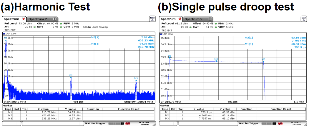
Some other general specifications of interest were tested, as shown in figure 4.The harmonic of the RFPA is below -30 dBc. Under the stress test,Single pulse droop is 0.18dBm during 8 ms.
Discussion
The test results show that the output power capability, linearity and output stability of RFPA meet the design specification, RFPA performs better in the face of mismatched load with negative feedback compensation strategy. However, when the load impedance is constant, the pre-distortion technique can achieve a better improvement for correcting the fixed nonlinearity caused by the power tube. So our further work focuses on combining them together for a better result.Conclusion
We present a 2kW non-magnetic RF power amplifier with negative feedback for 5T MRI proton imaging. It has high output power, high linearity and a strong ability of anti-load disturbance in the face of normal load mismatch.Acknowledgements
this work was supported in part the Strategic Priority Research Program of Chinese Academy of Sciences (Grant No. XDB25000000);National Key R&D Program of China, 2021YFE0204400; city grant RCYX20200714114735123;References
[1]Chen JF, Li Y, Zhang H, et al. High power RF amplifier for UHF MRI with configurable number of channels. ISMRM 2021 Abstract 1585.
[2] Orzada S, Solbach K, Gratz M, et al. A 32-channel parallel transmit system add-on for 7T MRI[J]. PLoS One. 2019;14(9):e0222452.
[3]Solbach K, Abuelhaija A, Shooshtary S. Near-Magnet Power Amplifier with built-in Coil Current Sensing. Proc Intl Soc Mag Reson Med 22. 2014:1287.
[4]Chu X, Yang X, Liu Y, et al. Ultra-low output impedance RF power amplifier for parallel excitation. Magn Reson Med.2009;61:952-961.
Figures