3237
Bumped Self-decoupled RF Coil
Ming Lu1, John C. Gore2,3, and Xinqiang Yan2,3
1College of nuclear equipment and nuclear engineering, Yantai University, Yantai, China, 2Vanderbilt University Institute of Imaging Science, Vanderbilt University Medical Center, Nashville, TN, United States, 3Department of Radiology and Radiological Sciences, Vanderbilt University Medical Center, Nashville, TN, United States
1College of nuclear equipment and nuclear engineering, Yantai University, Yantai, China, 2Vanderbilt University Institute of Imaging Science, Vanderbilt University Medical Center, Nashville, TN, United States, 3Department of Radiology and Radiological Sciences, Vanderbilt University Medical Center, Nashville, TN, United States
Synopsis
In this work, we propose a novel “bump” design to further improve the coil robustness versus loadings. For the loop-mode self-decoupled coil, the rotating magnetic field (composed of Bx and By) and electric field are mainly determined by the feed and arm conductors; the frequency shift that decreases coil robustness is mainly caused by the conductor with small-valued mode capacitors (referred to as mode conductor for short). Therefore, a bumped coil with a spaced mode conductor but unchanged arm and feed conductors potentially provides more robust tuning/matching performance without decreasing coil efficiency.
Introduction:
Self-decoupling has recently been proposed as a simple, efficient and robust approach to reducing the inter-element coil coupling in RF arrays [1]. In particular, it may be used for Tx coils as well as Rx coils as its mode of operation is independent of the subsequent circuit parameters such as preamplifier impedance [2]. Unlike conventional coils, the self-decoupled coil has an intentionally small capacitance, and thereby the resonant frequency and input impedance are more sensitive to the loading, which can lead to decreases of coil performance in practice. Previous work demonstrated large frequency shifts and mismatching could be alleviated by using multiple capacitors in series [1]. In this work, we propose a novel “bump” design to further improve the coil robustness versus loadings. For the loop-mode self-decoupled coil, the rotating magnetic field (composed of Bx and By) and electric field are mainly determined by the feed and arm conductors; the frequency shift that decreases coil robustness is mainly caused by the conductor with small-valued mode capacitors (referred to as mode conductor for short). Therefore, a bumped coil [3] with a spaced mode conductor but unchanged arm and feed conductors potentially provides more robust tuning/matching performance without decreasing coil efficiency.Methods:
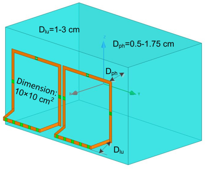
We first numerically investigated how the transmit (B1+), receive (B1-), and electric fields of 7T 10x10 cm2 bumped self-decoupled coils change with various spacings of the bumped conductor (Dlu in Figure 1, from 1 cm to 3 cm). A non-bumped self-decoupled coil (i.e., Dlu=0) was also simulated as a reference. Then we compared the performances of a pair of bumped self-decoupled coils (Dlu =2 cm). In this assessment, coils were well-tuned/matched/decoupled when the coil-to-phantom distance (Dph) is 1 cm. The coils were then moved closer or further away from the phantom, without re-tuning or re-matching. Dph was increased from 0.5 cm to 1.75 cm, in steps of 0.25 cm (Figure 1). The simulated frequency shift, impedance matching/mismatching at 298 MHz (Larmor frequency of 7T), and coil coupling/decoupling were recorded.Results:
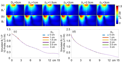
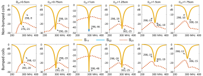
Figure 2a shows the normalized B1+ maps on central axial slices, with Dlu varying from 0 cm (non-bumped coil) to 3 cm. Figure 2c plots the 1D profiles of B1+ along the white-dotted lines in Figure 2a. The B1+ efficiency was not affected by the lift-up of the mode conductor. This is also true for normalized B1- maps, as shown in Figures 2b and 2d, which is expected based on reciprocity theory. A similar finding was also observed in the simulated E-fields in that bumped coils exhibit almost the same E-field strengths as the non-bumped coil (Figure 3).Figure 4 plots the impedance matching (evaluated by S11 and S22) and coil coupling performance (S21) of various bumped self-decoupled coils and the non-bumped self-decoupled coil. For both non-bumped and bumped coils, the inter-element isolation is superior (<-20 dB). As expected, the simulated non-bumped coil exhibits a large frequency shift (from 276 to 308 MHz) owing to the parasitic capacitance with the loading, while the bumped one has a lower frequency shift (from 283 to 306 MHz).
Discussions:
In addition to the loop-type self-decoupled coil studied here, the bump geometry could be extended to dipole-mode [4] self-decoupled coils. As a proof of concept, simple bumps were placed underneath part of the coil conductor. However, the bump geometries could be further optimized for better B1+ and E-field (SAR efficiencies). One more parameter to be optimized is the dielectric constant of the substrate underneath the bumped conductor, which here was set to 4 to mimic the dielectric constant of commonly used plastics.Conclusion:
We propose a novel bump design for self-decoupled coils to improve the tuning/matching robustness by lifting the mode conductor. It was found that the bumped conductor does not change the electromagnetic field inside the load and so does not decrease the B1+ efficiency or increase the local E-field/SAR.Acknowledgements
No acknowledgement found.References
- X. Yan, J. C. Gore, and W. A. Grissom, “Self-decoupled radiofrequency coils for magnetic resonance imaging,” Nat Commun, vol. 9, no. 1, p. 3481, Aug. 2018, doi: 10.1038/s41467-018-05585-8.
- P. B. Roemer, W. A. Edelstein, C. E. Hayes, S. P. Souza, and O. M. Mueller, “The NMR phased array,” Magnetic Resonance in Medicine, vol. 16, no. 2, pp. 192–225, 1990, doi: 10.1002/mrm.1910160203.
- A. Sadeghi-Tarakameh et al., “Improving radiofrequency power and specific absorption rate management with bumped transmit elements in ultra-high field MRI,” Magnetic Resonance in Medicine, vol. 84, no. 6, pp. 3485–3493, 2020, doi: 10.1002/mrm.28382.
- “The ‘Loopole’ Antenna: A Hybrid Coil Combining Loop and Electric Dipole Properties for Ultra-High-Field MRI.” https://www.hindawi.com/journals/cmrb/2020/8886543/ (accessed Nov. 01, 2021)
Figures

Figure 1 Simulation
model of a pair of bumped self-decoupled coils. Two coils (dimension 10x10 cm2)
are positioned 1cm apart. The distance between coil and phantom distance (Dph)
is from 0.5 cm to 1.75 cm. The lift-up (Dlu) of the bumped conductor is from 1 cm
to 3 cm. The electromagnetic properties of the cuboid phantom were set to: σ=0.6
and εr
= 78.

Figure 2 Simulated axial
B1+ (a) and B1- (b) maps (XY plane) with various lift-ups of the bumped
conductor (Dlu). (c) and (d): 1D profiles of B1+ and B1- along the
white-dotted lines in Figures 2a and 2b.

Figure 3 Simulated
coronal (YZ plane) E-field maps in the phantom. Top row: E-fields in the
coronal slice that is deep inside the phantom. Bottom row: E-fields in the coronal slice that is on the
surface of the phantom.

Figure 4 S-parameter plots of non-bumped (top row) and
2-cm-bumped (bottom row) with different coil-to-phantom distances (Dph). The
S11 and S22 plots representing impedance matching were shown in yellow while the S21
plots representing decoupling were shown in orange dotted lines.
DOI: https://doi.org/10.58530/2022/3237