3226
Design of ultrahigh dielectric constant uHDC helmet for 3T and its intrinsic resonance modes
Xinlian Chen1, Navid P. Gandji2, Christopher T. Sica2, Gary W. Yang3, Parisa Lotfi Poshtgol2, Hannes M Wiesner4, Xiao-Hong Zhu4, Michael Lanagan5, Wei Chen4, Qing X Yang2, and Xuegang Xin1
1Department of Biomedical Engineering, South China University of Technology, GuangDong, China, 2Departments of Neurosurgery and Radiology, College of Medicine, Pennsylvania State University, Hershey, PA, United States, 3Departments of Computer Science and Engineering, Pennsylvania State University, Hershey, PA, United States, 4Center for Magnetic Resonance Research, University of Minnesota, Minneapolis, MN, United States, 5Department of Engineering Science and Mechanics, Pennsylvania State University, Hershey, PA, United States
1Department of Biomedical Engineering, South China University of Technology, GuangDong, China, 2Departments of Neurosurgery and Radiology, College of Medicine, Pennsylvania State University, Hershey, PA, United States, 3Departments of Computer Science and Engineering, Pennsylvania State University, Hershey, PA, United States, 4Center for Magnetic Resonance Research, University of Minnesota, Minneapolis, MN, United States, 5Department of Engineering Science and Mechanics, Pennsylvania State University, Hershey, PA, United States
Synopsis
This investigation characterize the intrinsic resonance modes (IRM) in a helmet made from utrahigh dielectric constant (uHDC) material and their interactions with RF field produced by conventional array coils using numerical simulation. The RF field of the three lower order modes, TE, TM1 and TM2, were investigated. TM1 mode produces uniform H-field in the transverse plane inside the helmet similar to that of a birdcage coil. TM2 mode produces a strong RF field but with a large gradient. Understanding of the IRMs of large uHDC structures such as helmets provides theoretical foundation for wider applications of uHDC materials RF engineering.
Introduction
The ultra-high dielectric constant (uHDC) materials has been used to create helmets conformal to the human head. Experimental data acquired with uHDC helmet have demonstrated significant SNR improvements and transmit power reduction using a commercial receive array (Rx) at 3T1 or custom-built Rx at 7T2 and 10.5T3. However, the transmission field were shown to become very inhomogeneous with helmet with higher permittivity, though the total transmit power was significantly reduced. Since the uHDC helmet is a large continuous dielectric structure, in which the wavelength of the RF field is much shorter than the helmet dimension, a complicated set of intrinsic resonance modes (IRM) are produced in the helmet as a dielectric resonator. Little is known about the IRM of those irregular geometry such as the helmet in the current literatures. To optimize the uHDC helmet design, the goal of this investigation is to characterize the IRM and their interactions with and impacts on RF field produced by conventional transmission and receive array coils using numerical simulation.Methods
A helmet shaped shell was designed with uHDC material, consisting of an oval-shaped cylinder with a dome on top (Fig. 1). Helmet permittivity was set to 1000. The helmet was excited by waveguide port with E field along the z-direction to investigate the IRM as well as three selective coil elements of Siemens 20-Ch head receive array, named coil 7, coil 13 and coil 15, respectively. All coils were tuned and matched to 123.3 MHz, separately. Additionally, a head model (Ella) was placed in the helmet with excitation of coil 7 to predict the RF coil performance and enhancement in the human head without and with the uHDC helmet. All simulations were performed with Microwave Studio (Computer Simulation Technology, CST, Darmstadt,Germany), a full wave electromagnetic simulation software. The transmit efficiency was calculated by dividing the total B1+ field over the total accepted power by the coil4. SNR was calculated with a noise covariance-weighted root sum of squares reconstruction, using the simulated B1- and noise covariance matrix5,6.Results and Discussion
Fig. 2(A) shows S-parameter plot from waveguide ports, showing the excited IRMs of the helmet. Fig. 2(B) shows the corresponding E field and H field distributions of the first three modes excited by waveguide port 1. Fig. 3(A) shows the S11 plots from coil 7, coil 13 and coil 15. The same three lowest resonance modes can be simulated with all three coils with different attenuation values of S11 and slightly different frequency. However, the higher order IRMs in the higher frequency regime are very different. As shown in Fig. 3(B), the first mode produced transverse electric field with respective to the azimuthal axis (z-axis) and was named as TE mode. This mode is not excited by the waveguide port and therefore absent in the S11. The second and third mode produced transverse magnetic field and named as TM 1 and TM 2 mode, respectively. Most interestingly, the E field of TM 1 mode is mainly oriented in the z-direction, which produces a homogeneous H-field distribution similar to that of a birdcage coil. The TM 2 mode produces a field distribution similar to a magnetic quadruple, which produces an H-field with a strong linear gradient. When Ella’s head was loaded in the helmet, a characteristic of the S11 changed to a broader “hump” with a sharp resonance mode on top compared with baseline, as shown in Fig. 4(A). For both two cases, coil 7 was tuned and matched to 123.3 MHz. Fig. 4(B) and Fig. 4(C) show the E and H field for the baseline and with helmet at 123.3 MHz. As seen in the coronal view, the conservative E-field with Helmet is strong between the head and helmet. H field near the coil was reduced but enhanced over the entire head. As demonstrated in Fig. 5 and table 1, the receive sensitivity values are enhanced approximately by 23% in the brain compare to baseline. A significant SNR enhancement can be observed in the area away from the coil 7.Conclusion
A set of intrinsic dielectric resonance modes can be formed with a simple surface coil in a human-head-sized helmet made from uHDC materials. The RF field distributions of the three lower order modes, TE, TM1 and TM2, were investigated. TM 1 mode produces a uniform H-field in the transverse plane inside the helmet similar to that of a birdcage coil, which can be potentially used for excitation or MR spectroscopy with a surface coil. The SNR enhancement with this mode by the helmet is widespread to the entire head. TM 2 mode, on the other hand, produces a strong RF field but with a large gradient, which could be potentially used for RF encoding purpose. Understanding of the IRMs of large uHDC structures such as a helmet provides theoretical foundation for wider applications of uHDC materials RF engineering.Acknowledgements
This work is supported by National Natural Science Foundation of China (grant number 61929101).References
- Sica CT, Rupprecht S, Hou RJ, et al. Toward whole‐cortex enhancement with an ultrahigh dielectric constant helmet at 3T. Magn Reson Med. 2020;83(3):1123-1134.
- Lakshmanan K, Carluccio G, Walczyk J, et al. Improved whole-brain SNR with an integrated high-permittivity material in a head array at 7T. Magn Reson Med. 2021;86(2):1167-1174.
- Gandji NP, Sica CT, Lanagan MT, et al. Displacement current distribution on a high dielectric constant helmet and its effect on RF field at 10.5 T (447 MHz). Magn Reson Med. 2021. doi: 10.1002/mrm.28923.
- Ertürk MA, Raaijmakers AJE, Adriany G, Uğurbil K, Metzger GJ. A 16-channel combined loop-dipole transceiver array for 7 Tesla body MRI. Magn Reson Med. 2017;77(2):884-894.
- Kellman P, McVeigh ER. Image reconstruction in SNR units: a general method for SNR measurement. Magn Reson Med. 2005;54(6):1439-1447.
- Roemer PB, Edelstein WA, Hayes CE, Souza SP, Mueller OM. The NMR phased array. Magn Reson Med. 1990;16(2):192-225.
Figures
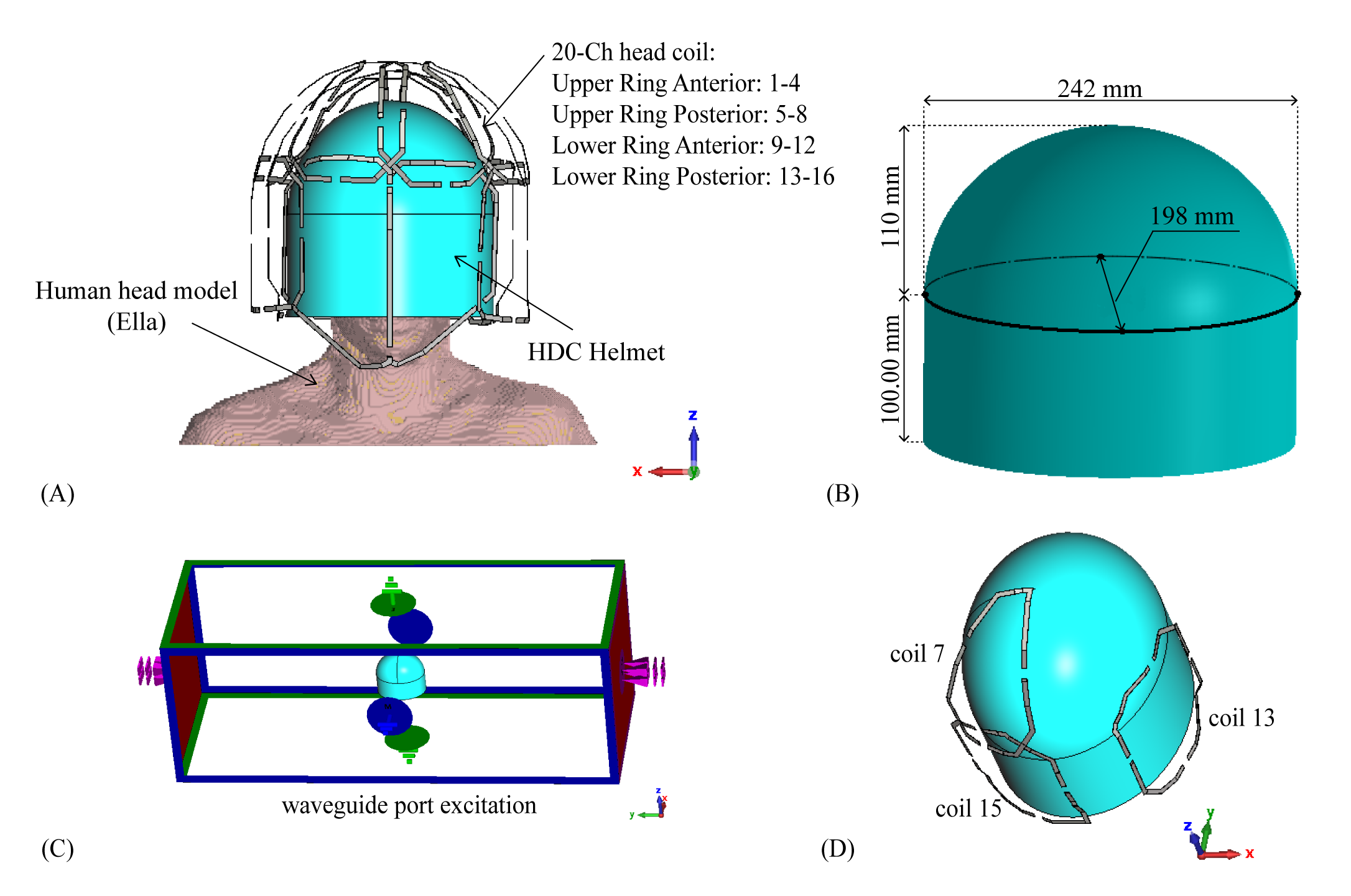
Figure 1. (A) The simulation setup a twenty-channel
head coil, a high dielectric constant (HDC) helmet and a human head model
(Ella). (B) The HDC helmet is a continuous structure with 5-mm thickness and
permittivity of 1000. (C) Helmet and waveguide port excitation: electric boundary was set at Zmin
and Zmax and magnetic boundary was set at Xmin and Xmax, so that E field was
along Z direction and H field was along X direction. (D) Helmet was simulated
with representative three coils, each coil was tune and matched separately.
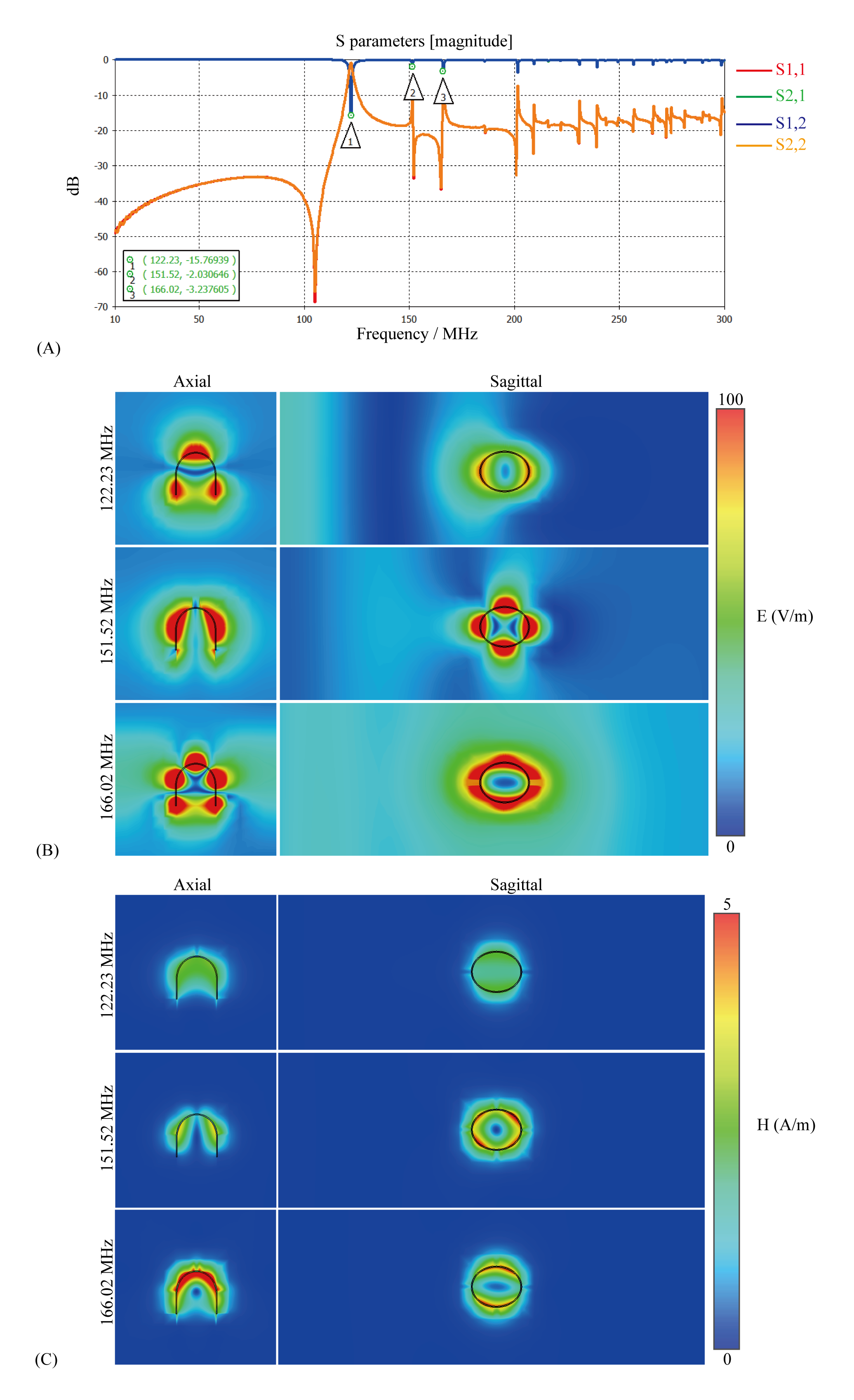
Figure 2. (A) S-parameter of waveguide
excitation. (B) Simulated E-field and (C) H-field of first three modes excited
by waveguide port 1 in center axial and sagittal planes.
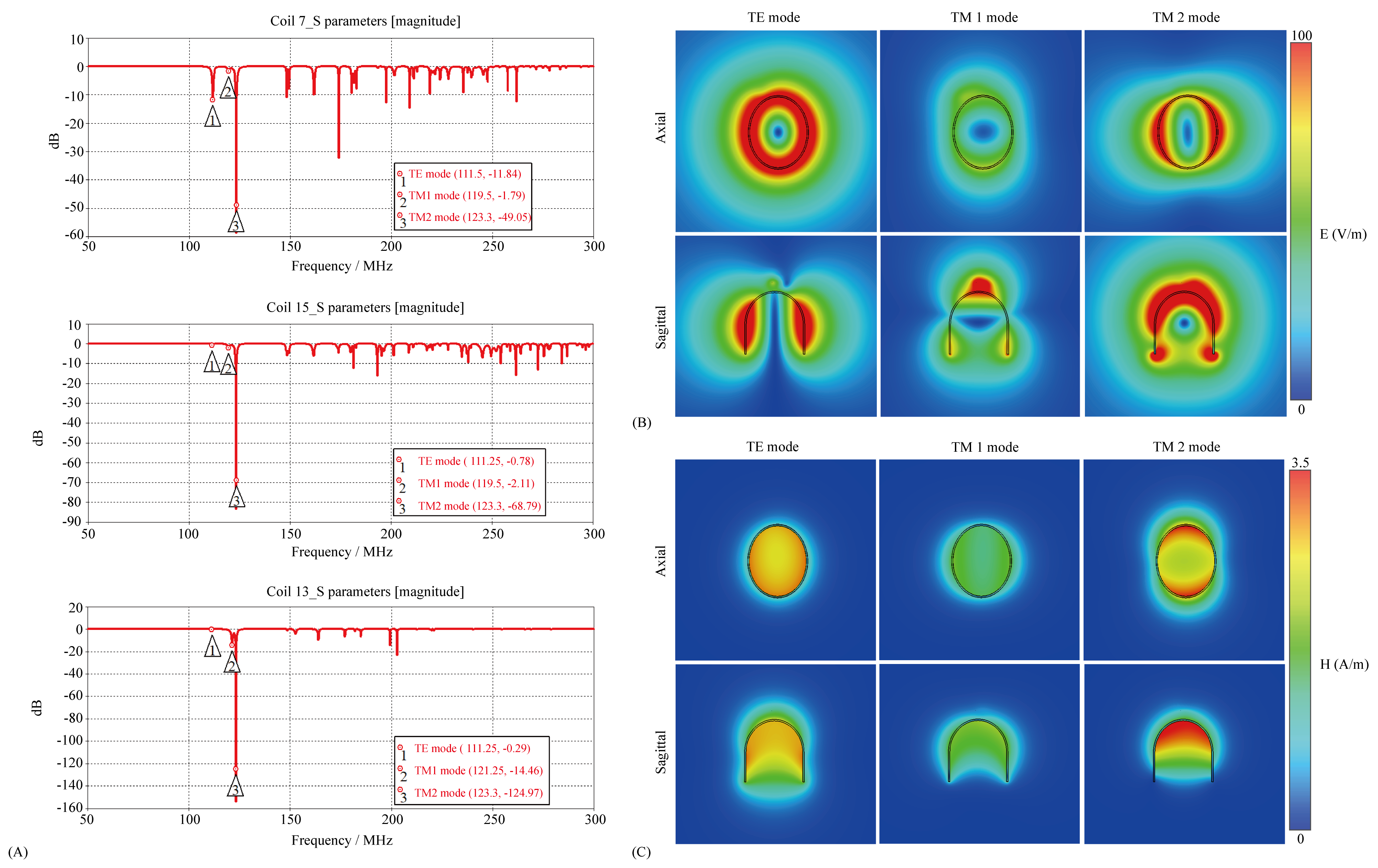
Figure 3 (A) S-parameter of coil 7, coil 13
and coil 15 excitation. All three coils coupled the helmet could produce the
same three modes. (B) Simulated E-field and (C) H-field of TE mode, TM1 mode
and TM2 mode.
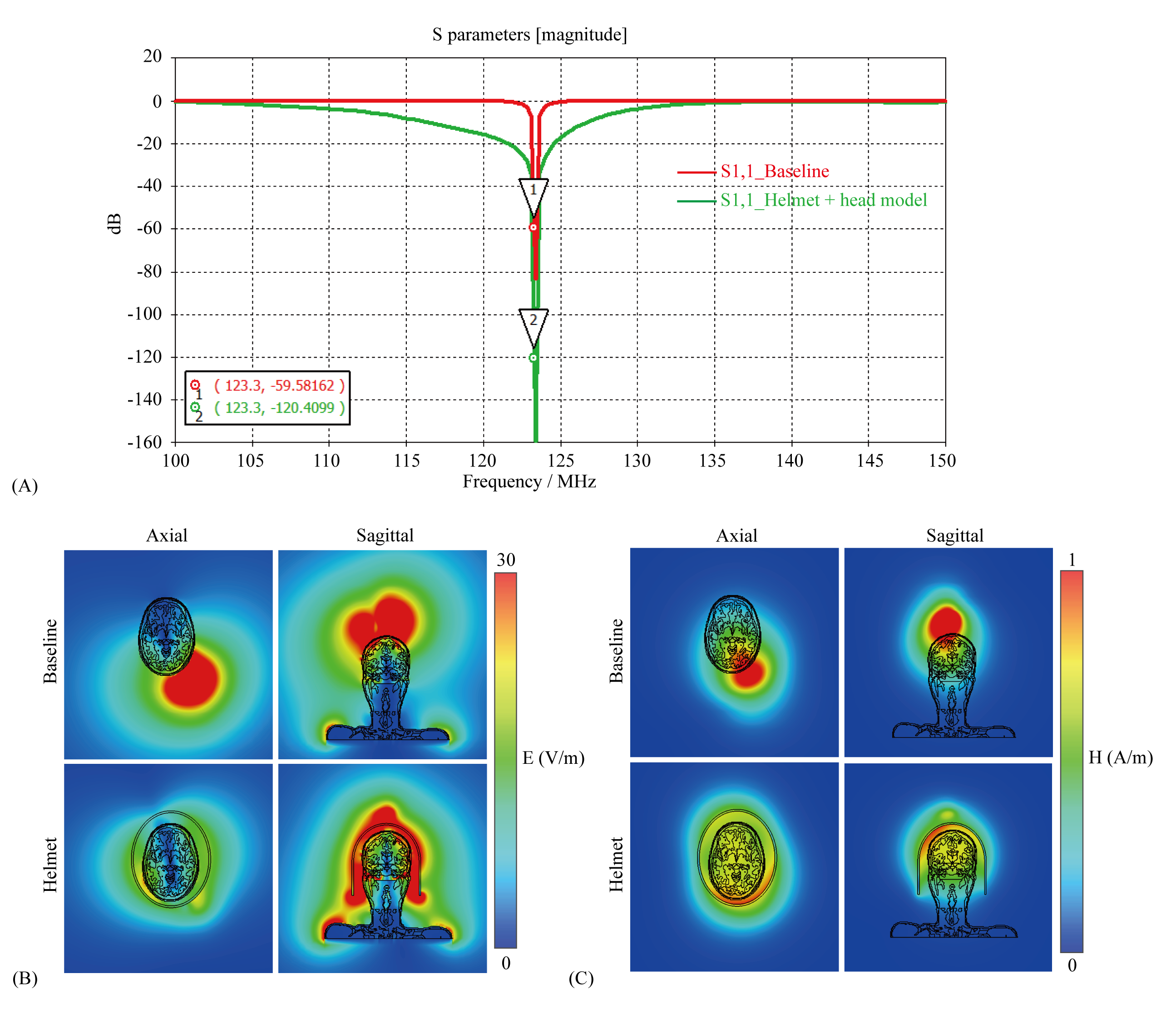
Figure 4. (A) S-parameter plot of coil 7
without (baseline) and with the helmet loaded with a human head model after
matching. (B) E-field and (C)
H-field are shown in center axial and sagittal planes. Under the resonance mode
of the helmet the RF field is coupled to the head more than the surface coil
alone and the distribution of the field spread out to the entire head.
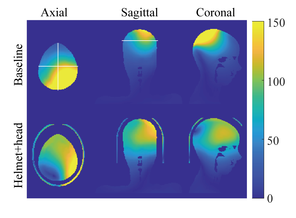
Figure 5. SNR maps
without (baseline) and with HDC helmet. The lines shown in axial and sagittal view of baseline demonstrate the positions of axial plane, sagittal plane and coronal plane.
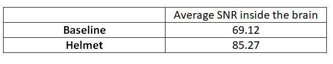
Table 1. Average SNR inside the brain of baseline and with helmet shell at 123.3 MHz. Approximate 23% SNR enhancement
by the helmet under resonance condition.
DOI: https://doi.org/10.58530/2022/3226