3224
Whole Spine Imaging at 5.0T Using An 8-channel Volume Transmit Coil and 48-channel Receive Array1Lauterbur Research Center for Biomedical Imaging, Shenzhen Institute of Advanced Technology, Chinese Academy of Sciences, Shenzhen, China, 2United Imaging Healthcare, Shanghai, China, 3Key Laboratory for Magnetic Resonance and Multimodality Imaging of Guangdong Province, Shenzhen, China
Synopsis
Large field-of-view imaging of spine in ultra-high field 5.0T magnetic resonance imaging system is achieved with RF hardware design of an 8-channel volume transmit coil and a dedicated posterior spine array of 48 receive channels. The axial coverage and transmit homogeneity allow the use of refocusing pulses under specific-absorption ratio limits by safety regulations. Consequent high-resolution fast spin echo clinical images are acquired and compared with results on a commercial 3.0T scanner.
Introduction
Ultra-high field (UHF) magnetic resonance imaging has advantages in increased signal-to-noise ratio (SNR) and high scan resolution, improved parallel imaging performance, and increased susceptibility-based contrast1,2. However, whole-body UHF imaging faces several challenges involving inhomogeneity of the radio-frequency transmit field (B1+), increased overall RF power deposition characterized by the global specific absorption ratio (SAR), and local SAR hot spots.3 Large FOV imaging in the ultra-high-field MRI system requires the implementation of a transmit array with volumetric coverage and a dedicated posterior receive array. The hardware system is designed and evaluated in the 5.0T MRI scanner and clinical images are acquired with satisfactory quality along the whole spine.Methods
In the 5T MRI scanner, a volume transmitting coil with 8 independent channels is designed and implemented to achieve whole-body excitation4. The major geometry of the transmit coil is defined as a 60 cm diameter inner bore size and an axial coverage of 45cm, corresponding to typical human spine imaging field of view size. The volume transmitting coil is designed and tuned with the aid of the electromagnetic simulation tool of CST Studio Suite®. A capacitive network5 is used to eliminate the coupling of the transmit array for adjacent and non-adjacent elements.The transmit array coil is driven by a set of 8 RF power amplifiers with independently controlled and synchronized amplitude and phase control. The transmit control consists of the transmit amplitude and phase, and the transmit power monitor and SAR control. Whole-body SAR is calculated with the 8 channel forward and reverse power with correction of the losses in the transmission path and reflections at coil input ports.
The receive posterior array is a 48-channel array designed for cervical, thorax, and lumbar spine imaging which covers the axial range over 1000mm and transversal field-of-view over 450mm.
The overall performance of the coil hardware is evaluated in the phantom test. A cylindrical phantom with a diameter of 170mm and length of 450mm is used with a filler of 1.24g NiSO4*6H2O and 5g NaCl per 1000ml water. The flip angle map is measured by the double-angle method with Gradient Echo of flip angle at 30 and 60 degrees, and TE/TR at 8ms/1000ms. A noise scan is acquired by setting the flip angle to zero for signal-to-noise ratio calculation.
Clinical image is acquired with T1-weighted Gradient Echo and Fast Spin Echo images. The Gradient Echo scan uses TE at 1.6ms and TR at 4.2ms with a FOV of 380*400mm and acquiring matrix 411*432. The Fast Spin Echo scan uses TE 9.5ms and TR 550ms with a FOV of 200*450mm and acquiring matrix 384*864. The resolution is 0.52 * 0.52 * 0.33mm in RO/PE/Slice direction respectively.
RESULTS
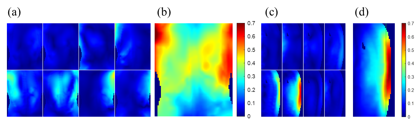
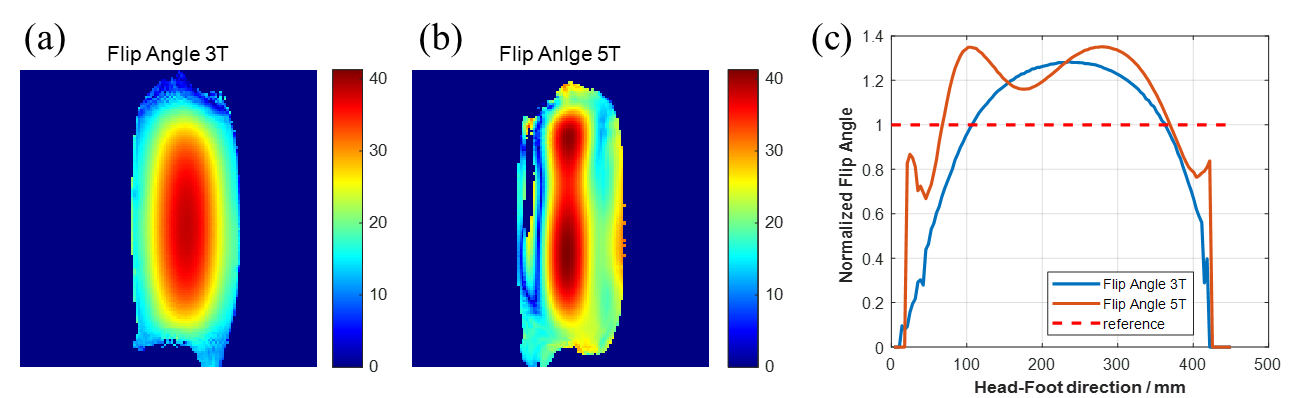
The B1+ field distributions for individual transmit elements are simulated in the human model and normalized to 1W incident power. The weighting factors for each channel are shimmed with by minimizing $$\sum_{\boldsymbol{n}=1}^{\boldsymbol{N}}{\left( \left| \boldsymbol{w}_{\boldsymbol{n}}\boldsymbol{b}_{\boldsymbol{n}}^{+}\left( \boldsymbol{r} \right) \right|-\boldsymbol{T}\left( \boldsymbol{r} \right) \right) ^2}$$. Results of the individual and combined B1+ distritution in coronal and sagittal plane along the spine region is shown in Figure 1.Transmit field coverage along the axial direction is evaluated in phantom tests with a sagittal plane scan and compared with results from a 3.0T MRI scanner. On the 3.0T scanner, the transmit field represented by the flip angle decreases monotonically from the center to either head or foot direction. On the 5.0T scanner, the transmit field distribution has a non-uniform distribution while maintaining overall coverage along the 450mm field of view along the axial direction.
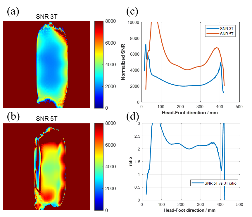
SNR map is calculated by the 30-degree flip angle gradient echo image and the reference noise image. The effect of inhomogeneous transmit field distribution is corrected by normalizing the SNR result to the measured flip angle map. The resulting ‘pure’ receive SNR is compared between the 5.0T and 3.0T result and a 2-fold SNR increase is observed along the axis of the phantom.
The acquired clinical images of Gradient Echo scan in the coronal plane and Fast Spin Echo scan in the sagittal plane are shown in Figure 4. A flip angle map is obtained at the same cross-section of the Fast Spin Echo image to estimate the transmit field distribution. The calculated standard deviation is 16.7% of the mean value of the measured flip angle along the axial direction at the spine region.
Discussions and Conclusions
The feasibility of large FOV whole spine imaging on the 5.0T MR scanner is demonstrated. With the help of the 8-channel transmit array, the axial transmit field distribution at 5.0T is comparable to 3.0T which facilitates large FOV imaging for the spine and torso region. The specific absorption rate is kept below regulation in the T1-weighted fast Spin Echo sequence. Clinical images with excellent homogeneity are achieved at the ultra-high-field 5.0T MR scanner.Acknowledgements
This work was supported in part National Key R&D Program of China, 2021YFE0204400; the Strategic Priority Research Program of Chinese Academy of Sciences (Grant No. XDB25000000); city grant RCYX20200714114735123.
References
1. Pohmann R, Speck O, Scheffler K. Signal-to-noise ratio and MR tissue parameters in human brain imaging at 3, 7, and 9.4 tesla using current receive coil arrays. Magn Reson Med. 2016;75(2):801-809. doi:10.1002/mrm.25677
2. Kraff O, Fischer A, Nagel AM, Mönninghoff C, Ladd ME. MRI at 7 Tesla and above: Demonstrated and potential capabilities. J Magn Reson Imaging. 2015;41(1):13-33. doi:10.1002/jmri.24573
3. Kraff O, Quick HH. 7T: Physics, safety, and potential clinical applications. J Magn Reson Imaging. 2017;46(6):1573-1589. doi:10.1002/jmri.25723
4. Fang F, Luo W, Gong J, Zhang R, Wei Z, Li Y. An 8-channel transmit loop array for body imaging at 5T. 2020;46(1):24-26.
5. Zhang X, Webb A. Design of a capacitively decoupled transmit/receive NMR phased array for high field microscopy at 14.1 T. J Magn Reson. 2004;170(1):149-155. doi:10.1016/j.jmr.2004.05.004
Figures