3221
Head Coil for Vertical-Field MRI using Loop/Dipole Parallel RF Coils1Innovative Technology Laboratory, FUJIFILM Healthcare Corporation, Tokyo, Japan, 2Radiation Diagnostic Systems Division, FUJIFILM Healthcare Corporation, Chiba, Japan
Synopsis
To improving the SNR and the g-factor in a vertical-field MRI, a multi-channel head coil has been developed. The coil consists of loop/dipole parallel RF coils (LDP) that improve the signal detection efficiency in the deep region of the subject in the vertical-field MRI. The performance of the coil was evaluated in a phantom experiment at 1.2T vertical-field MRI. The SNR and the g-factor of the coil using LDP were 1.2 and 1.2-2.9 times better than those of a conventional head coil, respectively. This technique will contribute to improve the performance of the vertical-field MRI.
Introduction
Multi-channel RF-array coils have a high SNR and a low g-factor due to high density placement on sample surfaces [1-3]. In horizontal-field MRI, the improvement of SNR using multi-channel has progressed rapidly because a loop coil providing high sensitivity when installed parallel to the sample axis can be used without limit of placement. On the other hand, in vertical-field MRI, the improvement of SNR using multi-channel has not progressed because the placement of the coil that can obtain sensitivity is limited. Therefore, it has become mainstream to use a quadrature detection (QD) coil array coil (QDA) using a large solenoid coil that can obtain high sensitivity in the deep region [4]. However, the QDA performance could not be further improved because the number of channels was limited due to the effect of magnetic coupling. To alleviate this problem, we previously proposed a loop/dipole parallel RF (LDP) coil for vertical-field MRI using an electromagnetic simulator that improves sensitivity [5,6]. In this study, we have developed a multi-channel array head coil using the LDP and evaluated its performance using 1.2 T vertical-field MRI.Methods
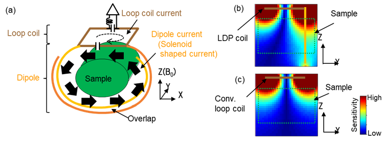
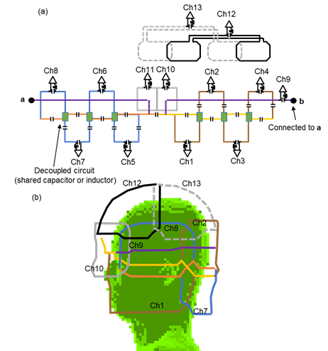
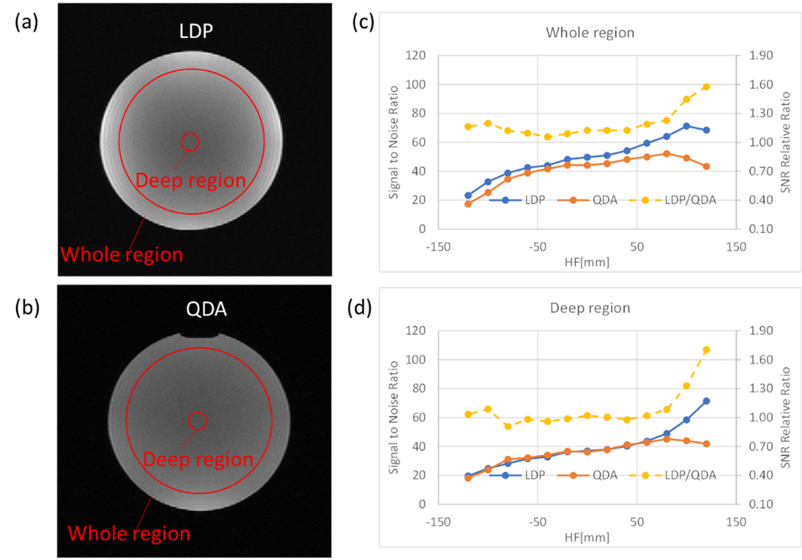
Fig. 1 (a) shows the basic configuration of a single-channel LDP coil. In the LDP coil, a loop coil and a dipole antenna were connected in parallel, and both ends of the dipole antenna partially overlap. The aim of the LDP was to operate the dipole antenna as a pseudo solenoid antenna to improve the signal detection efficiency. The loop coil was arranged along the subject, and the dipole antenna was arranged around the subject where Z is the direction of the magnetic field (B0). To form a solenoid shaped current at the dipole antenna, the resonance frequency of the dipole antenna is adjusted to about 15–35% higher than that of the loop coil. Figure 1 (b, c) shows a numerical-simulated sensitivity map of the single-channel LDP coil and a conventional same-size loop-array coil arranged at the X-Y plane. The LDP coil can obtain higher sensitivity in the deep region than in the conventional loop coil due to the sensitivity of the solenoid shaped current. Figure 2(a) shows an element block diagram of a developed multi-channel (13-ch) array head coil using a 9-ch LDP coil. Each loop coil of the LDP coil was connected to the single-dipole antenna via a capacitor. The magnetic couplings of adjacent coils are removed by using a shared capacitor or inductor. This LDP coil was arranged so that the dipole antenna makes two turns around the head, and the coils next to each other in the vertical and horizontal directions were arranged so that they partially overlap in order to remove the magnetic coupling (Fig. 2 (b)). In ch9, a solenoid coil was used instead of a loop coil of LDP, and an overlap and a shared capacitor were used to remove the magnetic coupling. In addition, two saddle coil elements (ch12,13) and two loop coil elements (ch10,11) were installed in the parietal region and the eye region, respectively. Imaging performance was evaluated with a 1.2 T MRI system (Spin-echo, TR/TE = 500/30 ms, thickness = 2 mm, FOV = 250 mm, and matrix size = 256 × 128). The comparison target was a conventional 5-ch QDA head coil consisting of a solenoid-saddle QD coil, and three counter rotating current (CRC) coils (Fig. 3(b,c)). A cylinder phantom (Diameter = 165 mm, Length = 320 mm, 10 mM NiCl2, and 0.25 w/v% NaCl solution) was used. The SNR was calculated by SNR = √(SHR-1S), where S is a vector of each coil sensitivity at the same pixel, and R is the noise correlation matrix calculated from E-fields [1].Results and Discussion
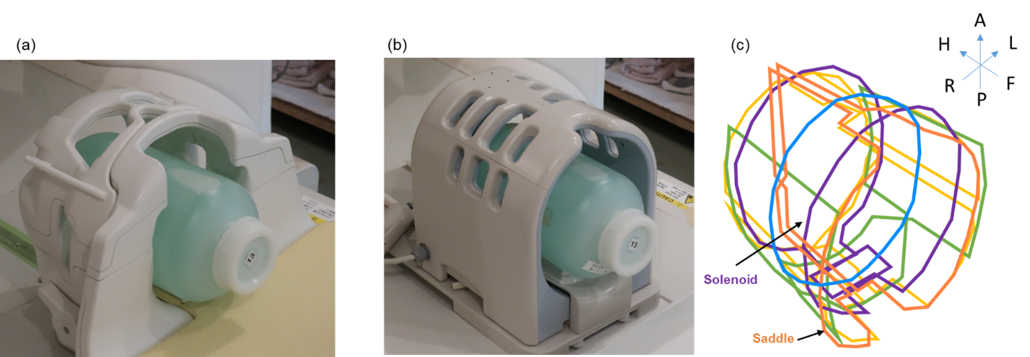
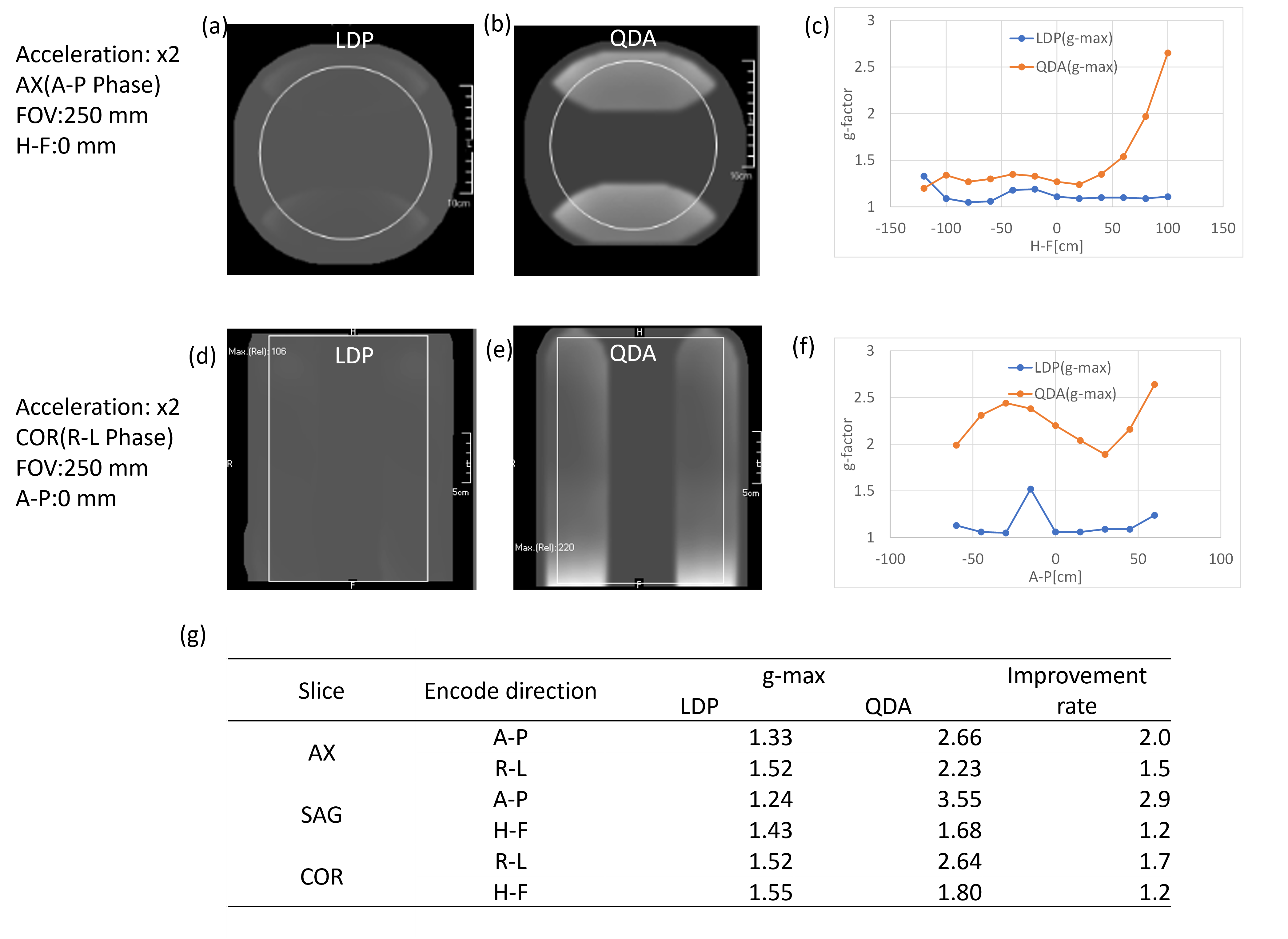
Figure 3 shows the developed head coil (LDP) and the conventional head coil (QDA). Figure 4(a,b) shows SNR maps of the LDP and the QDA, and Figure 4(c, d) shows its line profiles in the axial direction of the cylinder in the whole region (central 146-mm circular area) and the deep region (central 30-mm circular area), respectively. The improvement rates of the SNR were 1.20 and 1.08 for the wide and central areas, respectively. Figure 5 shows g-factor maps and their maximum value (g-max) line profiles of the LDP and the QDA. Figure 5(g) compares max values of g-factor for LDP and QDA. The improvement rates of the g-max were 1.2 to 2.9, and the g-factors in the R-L and A-P directions were significantly improved. These results indicate that the imaging performance of RF coil for the vertical-field MRI was improved, and at the same time, the coil placement limit was relaxed. In this study, a 13-channel array coil has been developed due to the limitation of the MRI system. However, the coil performance for vertical-field MRI will be further improved like that for horizontal-field MRI by increasing multi channels over 13.Conclusion
Imaging performance of the developed coil was higher than that of the conventional QDA due to the LDP technique. This technique will contribute to further improving the performance of vertical-field MRI.Acknowledgements
No acknowledgement found.References
1. Roemer PB, Edelstein WA, Hayes CE, et al. The NMR phased array. Magn Reson Med. 1990 Nov; 16 (2): 192-225.
2. Hardy CJ, Giaquinto RO, Piel JE, Rohling KW, Marinelli L, Blezek DJ, Fiveland EW, Darrow RD, Foo TK. 128-channel body MRI with a flexible high-density receiver-coil array. J Magn Reson Imaging. 2008 Nov; 28 (5): 1219-25.
3. Wiggins GC, Polimeni JR, Potthast A, Schmitt M, Alagappan V, Wald LL. 96-Channel receive-only head coil for 3 Tesla: design optimization and evaluation. Magn Reson Med. 2009 Sep; 62 (3): 754-62.
4. Takizawa M, Goto T, Mochizuki H, Nonaka M, Nagai S, Takeuchi H, Taniguchi Y, Ochi H, Takahashi T. Cardiac cine parallel imaging on a 0.7T open system. Magn Reson Med Sci. 2004 Apr 1; 3 (1): 45-9.
5. Ochi H, Yamamoto E, Sawaya K, Adachi S. Calculation of electromagnetic field of an MRI antenna loaded by a body. Proceedings of the 11th Annual Meeting of SMRM, Berlin; 1992. p. 4021.
6. Otake Y, Iwasawa K, Ochi H, Dohata M, Shimoda T. Loop Array RF Coil for Vertical Field MRI using Loop/Dipole Parallel RF Coils. Proceedings of the 27th Annual Meeting of ISMRM, Montreal; 2019. 1455.
Figures