2936
Velocity selective arterial spin labelling using parallel transmission
Chia-Yin Wu1,2,3, Jin Jin2,4, Carl Dixon1, Donald Maillet1, Markus Barth1,2,3, and Martijn Cloos1,2
1Centre for Advanced Imaging, The University of Queensland, Brisbane, Australia, 2ARC Training Centre for Innovation in Biomedical Imaging Technology, The University of Queensland, Brisbane, Australia, 3School of Information Technology and Electrical Engineering, The University of Queensland, Brisbane, Australia, 4Siemens Healthcare Pty Ltd, Brisbane, Australia
1Centre for Advanced Imaging, The University of Queensland, Brisbane, Australia, 2ARC Training Centre for Innovation in Biomedical Imaging Technology, The University of Queensland, Brisbane, Australia, 3School of Information Technology and Electrical Engineering, The University of Queensland, Brisbane, Australia, 4Siemens Healthcare Pty Ltd, Brisbane, Australia
Synopsis
In this work, we demonstrate a parallel transmit implementation of velocity selective arterial spin labelling (VSASL) at 7 Tesla on a custom flow phantom developed in house. The use of tailored pTx pulses can greatly mitigate the transmit field inhomogeneities present at higher field strengths. By manipulating the time symmetry of the pTx pulses in the VSASL module we were able to show significant improvement in velocity selective inversion fidelity.
Introduction
Ultra-high field MRI systems provide significant improvements in signal to noise ratio (SNR) and parallel imaging capability1, which can benefit SNR starved techniques such as velocity selective arterial spin labelling2 (VSASL). However, as the magnetic field strength increases, so does the resonance frequency needed to excite the spins. This translates to shorter radiofrequency wavelengths, which leads to a non-uniform transmit magnetic field (B1+)3. Parallel transmission (pTx)4,5 can be used to mitigate B1+ artefacts6,7. However, pTx implementations for advanced sequences, such as VSASL, have not yet been demonstrated. Here we evaluate the use of pTx pulses to improve VSASL at ultra-high field.Methods
pTx-Calibration: All data was collected using a Magnetom 7T Plus scanner (Siemens Healthcare, Erlangen, Germany) equipped with an 8x2kW parallel transmit system, and an 8Tx/32Rx head coil (Nova Medical, Wilmington, MA, USA) (Fig.1A). The SA2RAGE8 (TR=2400ms, TE=0.95ms, TD1,2=106ms,1800ms, 4x4x4mm3, iPAT=2) was used to measure the B1+ field in a circularly polarised (CP) mode, which was combined with a 2D interleaved GRE (TR=300ms, TE=3ms, 4×4×4mm3, iPAT=3) pulsing on individual channels to obtain quantitative B1+ maps for each channel9. Total calibration time was 3min.Sequence design: The VSASL preparation module (Fig.2) consists of a 90° tip-down pulse followed by bi-polar gradients to induce a 180° phase shift on spins with flowrate Vc. A 90° tip-up pulse is then applied inducing full 180° inversion on the spins flowing at Vc, while returning the stationary spins to equilibrium2. To mitigate ΔB0 effects, refocusing pulses are placed between the tip-up and tip-down pulses. In our protocol the VSASL preparation module was followed by with a 2D EPI readout (TR=10s, TE=20ms, 1.5x1.5x5.0mm3, iPAT=3).
Design of pTx pulses: Both the tip-down and tip-up 90° pulses in the VSASL preparation module were replaced with non-selective kT-points pulses7 (duration=2.62ms, 8 sub-pulses). The slice-selective excitation at the start of the EPI module was replaced with a 2-spoke10 solution (TBWP=3, sub-pulse duration=2ms). Both pTx pulses were designed with the spatial domain method11 using a magnitude least squares approach6. Two versions of the tip-up pulse were tested, both are phase inverted but one is also time reversed (Fig.3). The fidelity of these pulse VSASL combinations were evaluated in simulation and experiment.
Simulation: Bloch simulations were performed to evaluate the benefits of pTx in the VSASL sequence. Specifically, flow was modelled by dynamically updating the spatial coordinates of the isochromats in the simulation (time step=10us, isochromats=150 per voxel). The normalised root mean square error (NRMSE) was calculated to evaluate the pulse performance.
Phantom experiments: For experimental validation, we used an in house developed flow phantom (Fig.1B). An Arduino (UNO Rev3) was used to control the rate of flow (approx. 2cm/s) in the 4 tube sections housed in the main body of the phantom. To illustrate the behaviour of the VSASL module the flow encoding gradients were varied from 0 to 60000ms*uT/m. When using the CP-mode implementation the reference voltage was calibrated to achieve a 90° flip angle excitation in the centre of the phantom.
Results & Discussion
Simulation: Simulations of the VSASL preparation module are shown in Fig.4. The B1+ non-uniformities in the tip-down, tip-up and excitation pulses have a significant impact on the contrast fidelity in CP-mode (NRMSE of 0.47, see Fig.4A,B). The majority of B1+ artefacts can be mitigated using kT-points. However, simple phase inversion of the kT-points tip-up pulse leaves considerable residual magnetisation behind (NRMSE of 0.22, see Fig.4C). As might be expected, based on the time symmetry of the design problem, the time reversed solution performed markedly better (NRMSE of 0.09, see Fig.4D).Phantom experiment: Our pTx solution demonstrates a significant improvement in signal and contrast uniformity (Fig.5A). Using the CP-mode fails to invert the flowing spins in the outer tubes, whereas our pTx solution achieves inversion in all tubes (Fig.5B). However, a slight variation was observed in the flow-encoding gradient moments required for full inversion amongst different tubes. This may be attributed to small differences in effective flowrate due to turbulence. Looking beyond the flow velocity selective inversion fidelity, we observe that the combination of kT-points and spokes pulses produces a much more uniform magnetisation throughout the slice, which will translate into a higher SNR in areas where the CP-mode produces a low B1.
Although effective, the adiabatic refocusing pulses are SAR intensive. Considering that 7 Tesla is relatively SAR constrained, it would be preferable to also replace these with large-tip-angle pTx pulses12. Moreover, this can potentially reduce the refocusing pulse durations and therefore shorten the minimum separation time between the encoding gradients. In turn, this will reduce sensitivity to B0 inhomogeneity. The next stage would be to evaluate our pTx VSASL solution in vivo.
Conclusion
We have shown that pTx can significantly improve the SNR and contrast fidelity of VSASL at 7 Tesla, which could help make ASL more accessible and robust at ultra-high field.Acknowledgements
This research was conducted by the Australian Research Council Training Centre for Innovation in Biomedical Imaging Technology (project number IC170100035) and funded by the Australian Government. The authors acknowledge the facilities of the National Imaging Facility at the Centre for Advanced Imaging.References
- Uğurbil K. Magnetic Resonance Imaging at Ultrahigh Fields. IEEE Trans Biomed Eng. 2014;61(5):1364-1379.
- Wong EC, Cronin M, Wu WC, et al. Velocity-selective arterial spin labeling. Magn Reson Med. 2006;55(6):1334-1341.
- Vaughan JT, Garwood M, Collins CM, et al. 7T vs. 4T: RF Power, Homogeneity, and Signal-to-Noise Comparison in Head Images. Magn Reson Med. 2001;46(1):24-30.
- Katscher U, Bornert P, Leussler C, et al. Transmit SENSE. Magn Reson Med. 2003;49(1):144-150.
- Zhu Y. Parallel excitation with an array of transmit coils. 2004;51(4):775-784.
- Setsompop K, Wald LL, Alagappan V, et al. Magnitude least squares optimization for parallel radio frequency excitation design demonstrated at 7 Tesla with eight channels. Magn Reson Med. 2008;59(4):908-915.
- Cloos MA, Bouland N, Ferrand E, et al. kT-points: Short three-dimensional tailored RF pulses for flip-angle homogenization over an extended volume. Magn Reson Med. 2012;67(1):72-80.
- Eggenschwiler F, Kober T, Magill AW, et al. SA2RAGE: a new sequence for fast B1+ mapping. Magn Reson Med. 2012;67(6):1609-1619.
- Van de Moortelle PF, Snyder C, DelaBarre L, et al. Calibration tool for RF shim at very high field with multiple element rf coils: from ultra fast local relative phase to absolute magnitude B1+ mapping. In Proc. of the 15th Annual Meeting of the ISMRM. Berlin, Germany. 2007;p1676.
- Saekho S, Yip C, Douglas C, et al. Fast-kz three-dimensional tailored radiofrequency pulse for reduced B1 inhomogeneity. Magn Reson Med. 2006;55(4):719-724.
- Grissom W, Yip C, Zhang Z, et al. Spatial Domain Method for the Design of RF Pulses in Multicoil Parallel Excitation. Magn Reson Med. 2006;56(3):620-629.
- Xu D, King KF, Zhu Y, et al. Designing multichannel, multidimensional, arbitrary flip angle RF pulses using an optimal control approach. Magn Reson Med. 2008;59(3):547-560.
Figures
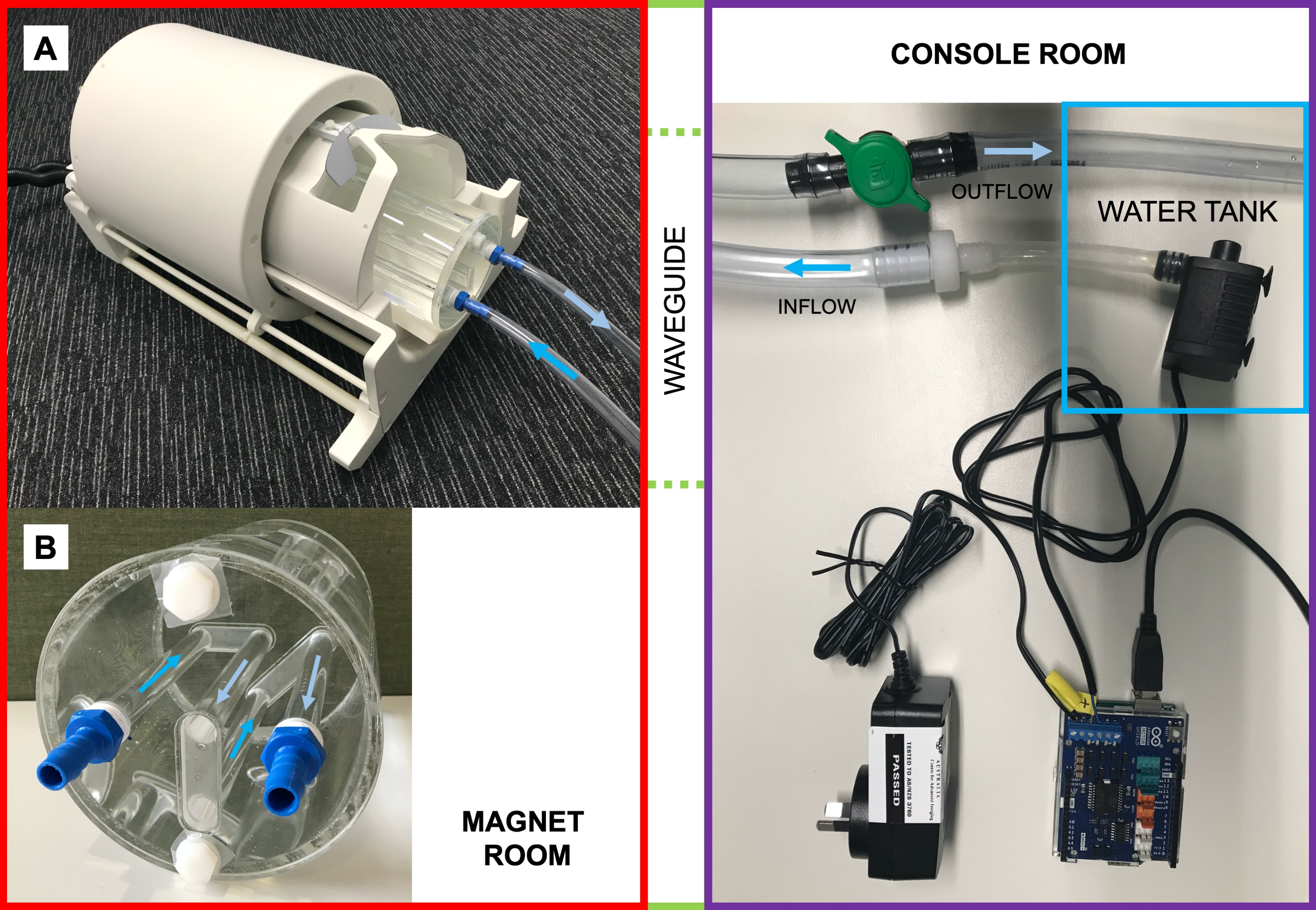
Fig.1: Custom made flow phantom setup. The water tank and pump control system are setup in the MR console room with connected inflow and outflow tubes fed through the waveguide to the flow phantom which is positioned (A) in the Nova Medical 8Tx/32Rx head coil. Variable flowrate is implemented using PWM pump control via a microcontroller and additional backpressure control with a manual valve. (B) Arrows indicate the flow direction in the tubes housed inside the custom flow phantom.
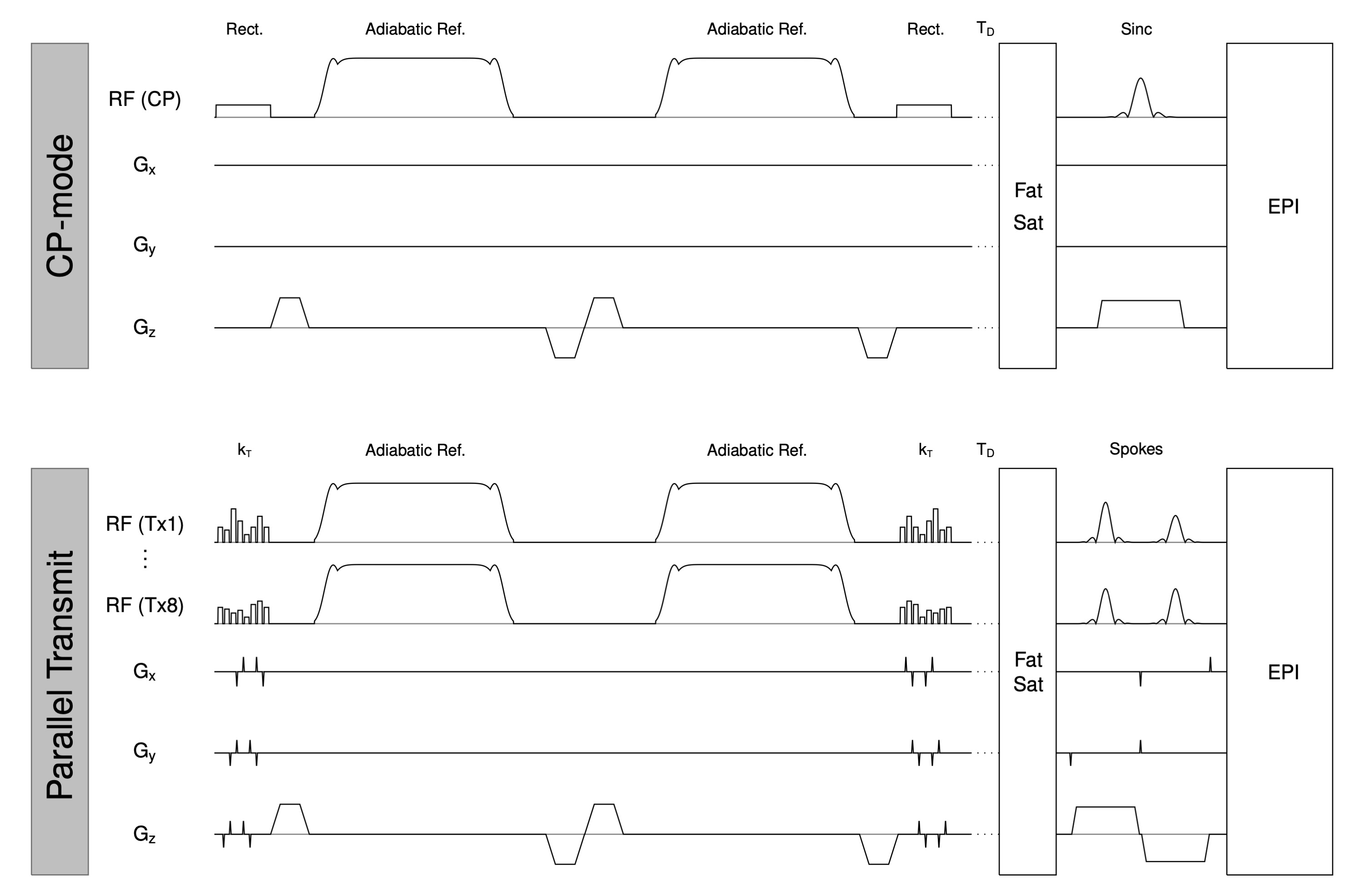
Fig.2: VSASL sequence diagram for single channel (CP-mode) and parallel transmit implementation. For the pTx implementation we replace the tip-down, tip-up rectangular pulses and sinc excitation pulse with our tailored pTx kT-points and spoke pulses respectively. TD=time delay.
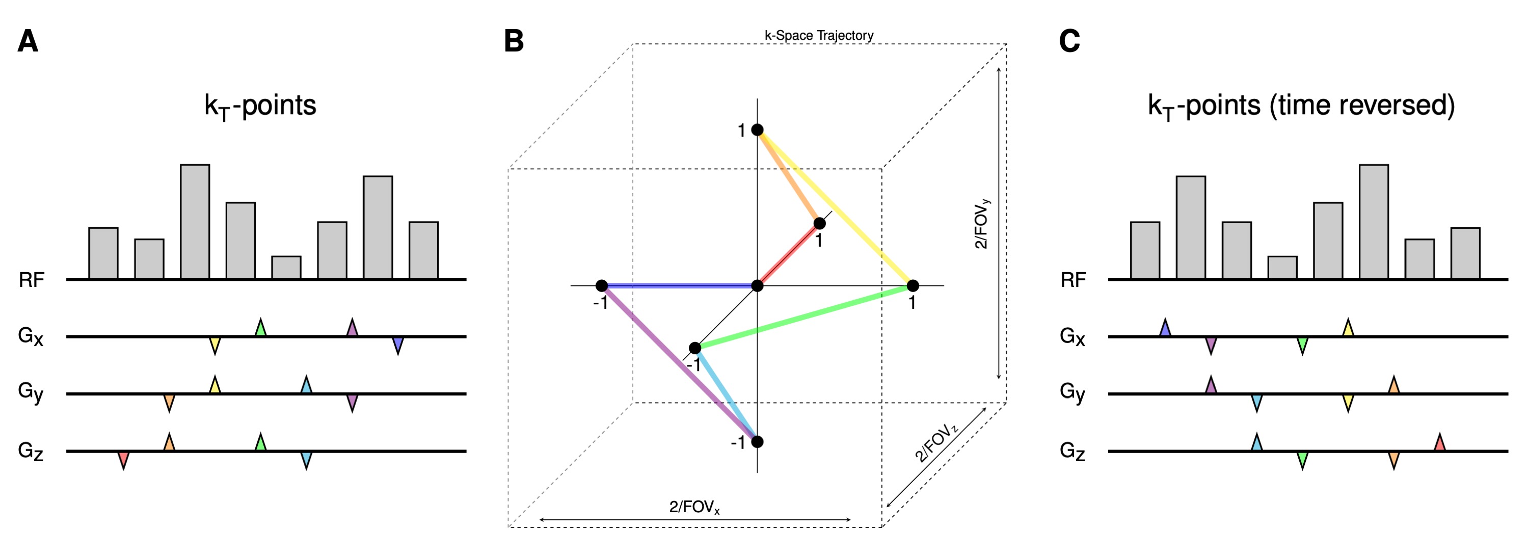
Fig.3: Example kT-point pulse solution for one of the eight RF transmit channels and three gradient axes. Radiofrequency subpulse train and gradient blips designed for two versions of the tip-up pulse: (A) inverted RF phase and (C) inverted RF phase plus time reversal where the subpulse train and k-space trajectory are reversed. (B) The trajectory used to move between points in transmit k-space. Gradient blips are colour-coded to show the corresponding segment of the trajectory.
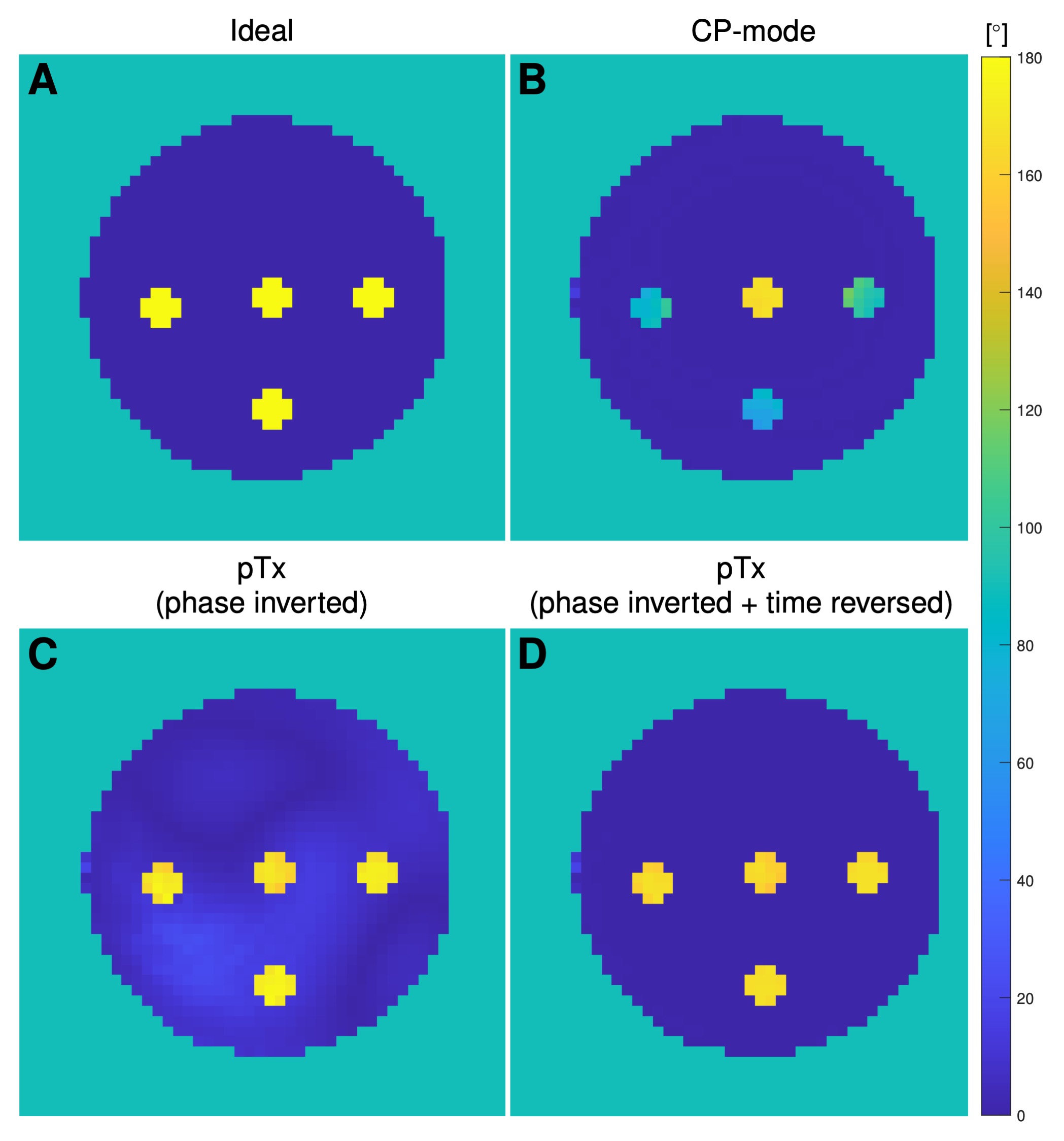
Fig.4: Simulated flip angle maps of the VSASL preparation module based on B1+ maps measured in the phantom. Both stationary spins (single large ROI) and flowing spins (4 smaller ROIs) are simulated for the following cases: (A) ideal, (B) CP-mode, (C) pTx – phase inverted and (D) pTx – phase inverted plus time reversed.
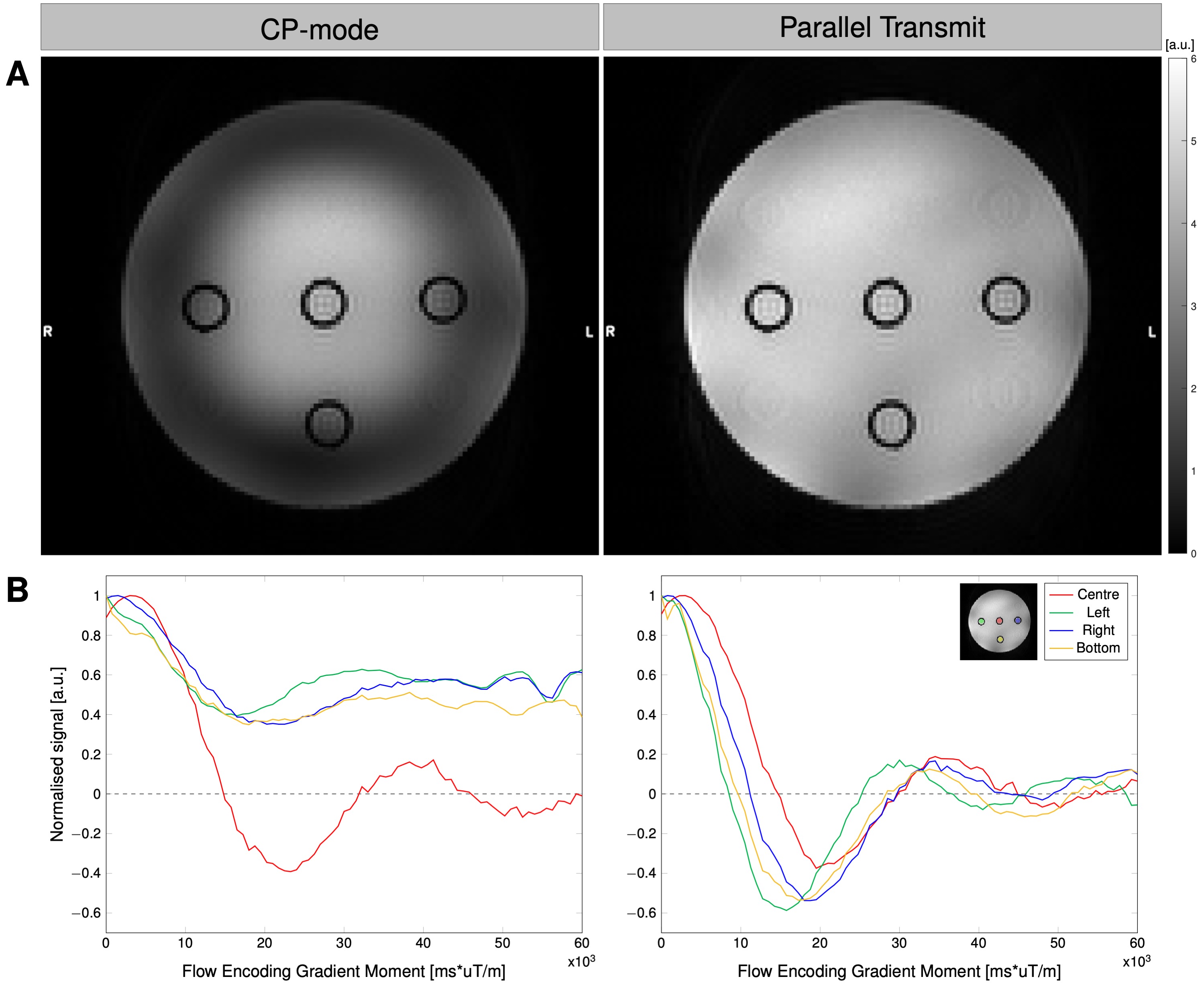
Fig.5: Flow phantom experimental results. (A) SNR maps measured using single channel (CP-mode) and parallel transmit. (B) Normalised signal for each tube for varying levels of gradient flow encoding. Average taken over four repetitions.
DOI: https://doi.org/10.58530/2022/2936